A pool bottom structure for producing ultra-clear glass

A technology of ultra-clear glass and pool bottom, applied in glass furnace equipment, glass manufacturing equipment, furnaces, etc., can solve the problems of unfavorable microbubble clarification and dispersal, great influence of reflux at clarification place, thick glass flow layer, etc., to achieve Improve homogenization and clarification effects, improve melting efficiency, and reduce viscous layers

Active Publication Date: 2019-04-16
彩虹(合肥)光伏有限公司
View PDF3 Cites 0 Cited by
  • Summary
  • Abstract
  • Description
  • Claims
  • Application Information

AI Technical Summary

Problems solved by technology

[0002] Ultra-clear glass is a kind of ultra-transparent low-iron glass. It is a high-quality, multi-functional new type of high-end glass with a light transmittance of over 91.5%. In normal production of ultra-clear glass, there are two strands in the melting furnace. The glass liquid flow with opposite circulation direction, one is the feeding liquid flow before the hot spot, and the other is the forming liquid flow after the hot spot. The glass liquid flow moves to the neck of the discharge port as a whole during the circulation process. Glass melting furnaces usually adopt a flat bottom or pool bottom structure with inclined steps. Although this structure is simple and convenient for construction, the rear pool is deeper and the glass flow layer is thicker, which is not conducive to the clarification and release of microbubbles. Higher, it is greatly affected by the reflux at the clarification point, and when the amount of extraction changes greatly, it will cause large fluctuations in the quality of the glass liquid

Method used


Image

  • A pool bottom structure for producing ultra-clear glass
  • A pool bottom structure for producing ultra-clear glass

Examples


Embodiment 1

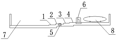
[0022] This program is implemented in this way, please refer to figure 1 and figure 2 .

[0023] 1. Structural composition. Before the hot spot at the feeding port 7 at the bottom of the pool, the feeding liquid flow will be formed, causing fluctuations in the fluctuating liquid flow at the bottom of the pool. The other is the forming liquid flow at the clarification place after the hot spot. The first step 1 is set on the right side of the feeding port 7, the height is 0.1m, the second step 2 is set on the right side of the first step 1, the height is 0.1m, and the third step 3 is set on the right side of the second step 2, and the height is 0.1m m, the right side of the third step 3 is provided with the fourth step 4 with a height of 0.1m, a kiln ridge 6 is set on the right side of the fourth step 4, the height of the kiln ridge 6 is 0.75m, and the depth of the clarification part 8 is 1.1m. The mouth 7 has a depth of 1.5m. Preferably, a plurality of grooves are arranged l...

Embodiment 2

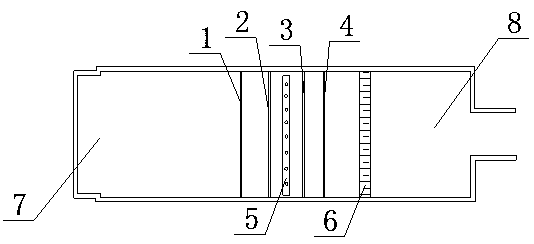
[0025] This program is implemented in this way, please refer to figure 1 and figure 2 .

[0026] Structural composition, the feeding port 7 at the bottom of the pool is before the hot spot, and the feeding liquid flow will be formed, causing the fluctuating liquid flow at the bottom of the pool to fluctuate, and the other is the forming liquid flow at the clarification place after the hot spot. The first step 1 is set on the right side of the place 7, and the height is 0.2m. The second step 2 is set on the right side of the first step 1, and the height is 0.2m. The third step 3 is set on the right side of the second step 2, and the height is 0.2m. The right side of the third step 3 is provided with a fourth step 4 with a height of 0.2m. A kiln ridge 6 is set on the right side of the fourth step 4. The height of the kiln ridge 6 is 0.5m, the depth of the clarification is 0.7m, and the feeding port is 7 The depth is 1.5m. Preferably, multiple grooves are arranged horizontally...


PUM

PropertyMeasurementUnit
heightaaaaaaaaaa
depthaaaaaaaaaa
transmittivityaaaaaaaaaa

Abstract

The invention discloses a pool bottom structure for producing ultra clear glass. The pool bottom structure comprises a feed port part (7) and a clarification part (8); a first step (1), a second step (2), a third step (3) and a fourth step (4) which are sequentially higher are arranged at the right side of the feed port part (7), a bubbling device (5) is arranged in the middle of the second step (2), a furnace ridge (6) is arranged at the right side of the fourth step (4), and the clarification part (8) is arranged at the right side of the furnace ridge (6). The pool bottom structure for producing the ultra clear glass can accelerate discharging of microbubbles and lower the hot spot temperature and has the advantages of accelerating clarification, blocking reflux of clarified and homogenized glass liquid and stabilizing glass liquid flow.

Description

technical field [0001] The invention relates to the field of glass production, in particular to a pool bottom structure for producing ultra-clear glass. Background technique [0002] Ultra-clear glass is a kind of ultra-transparent low-iron glass. It is a high-quality, multi-functional new type of high-end glass with a light transmittance of over 91.5%. In normal production of ultra-clear glass, there are two strands in the melting furnace. The glass liquid flow with opposite circulation direction, one is the feeding liquid flow before the hot spot, and the other is the forming liquid flow after the hot spot. The glass liquid flow moves to the neck of the discharge port as a whole during the circulation process. Glass melting furnaces usually adopt a flat bottom or pool bottom structure with inclined steps. Although this structure is simple and convenient for construction, the rear pool is deeper and the glass flow layer is thicker, which is not conducive to the clarificatio...

Claims


Application Information

Patent Timeline
Patent Type & Authority Patents(China)
IPC IPC(8): C03B5/04C03B5/193
CPCC03B5/04C03B5/193
Inventor 仝小飞张文斌李达宏李娟
Owner 彩虹(合肥)光伏有限公司
Why Eureka
Try Eureka