
Optical frequency shift inhabitation method of SERF atom magnetometer

A technology of atomic magnetic intensity and optical frequency shift, which is applied to the size/direction of the magnetic field, the use of magneto-optical equipment for magnetic field measurement, and the measurement of magnetic variables. It can solve problems such as dependence on measurement accuracy and achieve high suppression accuracy.

Active Publication Date: 2016-12-14
BEIHANG UNIV
View PDF2 Cites 20 Cited by
  • Summary
  • Abstract
  • Description
  • Claims
  • Application Information

AI Technical Summary

Problems solved by technology

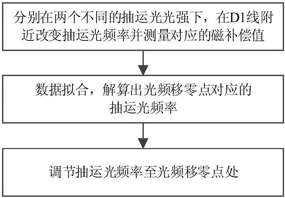
[0004] The problem solved by the present invention is: to overcome the problem that the existing optical frequency shift suppression method relies on the measurement accuracy of the spectral line center of the atomic absorption spectrum, to provide a high-precision method for suppressing the optical frequency shift of the SERF atomic magnetometer, using the three-dimensional principle Potential magnetic compensation technology, by measuring the pumping optical frequency and its corresponding magnetic compensation value under two sets of different light intensities, the zero point of optical frequency shift is calculated

Method used


Image

  • Optical frequency shift inhabitation method of SERF atom magnetometer
  • Optical frequency shift inhabitation method of SERF atom magnetometer
  • Optical frequency shift inhabitation method of SERF atom magnetometer

Examples


Embodiment Construction

[0019] like figure 1 Shown, the specific implementation steps of the present invention are as follows:

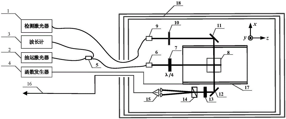
[0020] (1) Realize that the experimental device utilized by the present invention is as figure 2 shown. Wherein the alkali metal gas chamber 8 is installed in the shielding barrel 18 and heated until the alkali metal atomic number density reaches 10 13 ~10 14 piece / cm 3 order of magnitude to ensure that the atom works in the SERF state. Adjust the frequency of the laser light output by the pump laser 2 to the vicinity of the alkali metal atom D1 line. After the output laser light is split by the optical fiber beam splitter 5, one beam enters the wavelength meter 3 for monitoring its frequency, and the other beam passes through the optical fiber The collimator 6 converts it into spatial light, and then passes through the 1 / 4 wave plate 7 to become circularly polarized light to irradiate the alkali metal gas cell 8 to realize the pumping of atoms. The laser output from...


PUM


Abstract

The invention relates to an optical frequency shift inhabitation method of an SERF atom magnetometer. In the normal optical frequency shift inhabitation method of an SERF atom magnetometer, the frequency of the pumping light is adjusted to be in the center of a spectral line of an atomic absorption spectrum. However, an alkali metal air chamber of the SERF atom magnetometer is characterized by high atomic density and big buffering gas pressure, so the center of the spectral line is hard to obtain. Therefore, the definition of the normal optical frequency shift inhabitation method is not high. According to the optical frequency shift inhabitation method provided by the invention, under two different pumping light strengths, by combining the three dimensional in-situ magnetic compensation technology, the size of the magnetic field sensed by atoms corresponding to the different pumping light frequencies is measured, and theoretic fitting and resolving on the measured data, so optical frequency shift null points can be precisely found, thereby achieving sufficient inhabitation of the optical frequency shift. The optical frequency shift inhabitation method provided by the invention is independent of measurement of the atomic absorption spectrum, and the optical frequency shift inhabitation level depends on the precision of the magnetic compensation, so compared with the normal method, the optical frequency shift inhabitation method provided by the invention is quite high in inhabitation precision.

Description

technical field [0001] The invention relates to a method for suppressing optical frequency shift of a SERF (Spin-Exchange-Relaxation-Free) atomic magnetometer, which belongs to the field of atomic magnetometers and can also be used in the field of atomic spin gyroscopes. Background technique [0002] Optical frequency shift is a common error in atomic magnetometers. When circularly polarized pump light acts on atoms, the ACstark effect will cause the Zeeman energy level of the atoms to shift, resulting in optical frequency shift. For an atomic magnetometer it acts as a "false" magnetic field, thus causing measurement errors. [0003] The SERF atomic magnetometer is an ultra-high-sensitivity atomic magnetometer. The conventional optical frequency shift suppression method is to adjust the frequency of the pump light to the center of the spectral line of the atomic absorption spectrum. The disadvantage of this method is that it depends on the spectral line measurement accuracy...

Claims


Application Information

Patent Timeline
Patent Type & Authority Applications(China)
IPC IPC(8): G01R33/00G01R33/032
CPCG01R33/0029G01R33/032
Inventor 房建成钱政陆吉玺尹彦胡朝晖刘刚
Owner BEIHANG UNIV
Learn More