Full-automatic air panoramic data collection system and method, and control terminal

A data acquisition system and control terminal technology, applied in non-electric variable control, attitude control, height or depth control, etc., can solve the problems of small shooting range, low acquisition efficiency, difficult to complete, etc., to expand the scope and applicability , Improve work efficiency and reduce battery power consumption

Inactive Publication Date: 2016-12-14
广州优飞信息科技有限公司
View PDF6 Cites 11 Cited by
  • Summary
  • Abstract
  • Description
  • Claims
  • Application Information

AI Technical Summary

Problems solved by technology

[0013] (1) The shooting range is small, and it needs to be manually controlled by the remote control. It can only be shot within the line of sight, and the general distance is about 120 meters;
[0014] (2) The positioning accuracy is low. The position and altitude of the aircraft are all judged by artificial vision, and it is difficult to accurately reach the specified position and altitude.
[0015] (3) It can only be used for consumer entertainment and cannot be used in industry applications
Due to the low positioning accuracy of manual control, it is difficult to complete the industrial applications with high position requirements;
[0016] (4) It is difficult to guarantee the quality of shooting. The key link to ensure the quality of 360 panoramic shooting is to fix the position of the aircraft
Due to the manual control of the aircraft, while hovering, rotating, and adjusting the lens to shoot, it is relatively difficult, especially the wind speed and airflow in the air are more complicated, so the quality of the shooting results is low.
[0017] (5) The efficiency is low. For each point, more than 20 photos need to be collected, all relying on manual control, and the collection efficiency is very low.

Method used


Image

  • Full-automatic air panoramic data collection system and method, and control terminal
  • Full-automatic air panoramic data collection system and method, and control terminal
  • Full-automatic air panoramic data collection system and method, and control terminal

Examples


Embodiment Construction

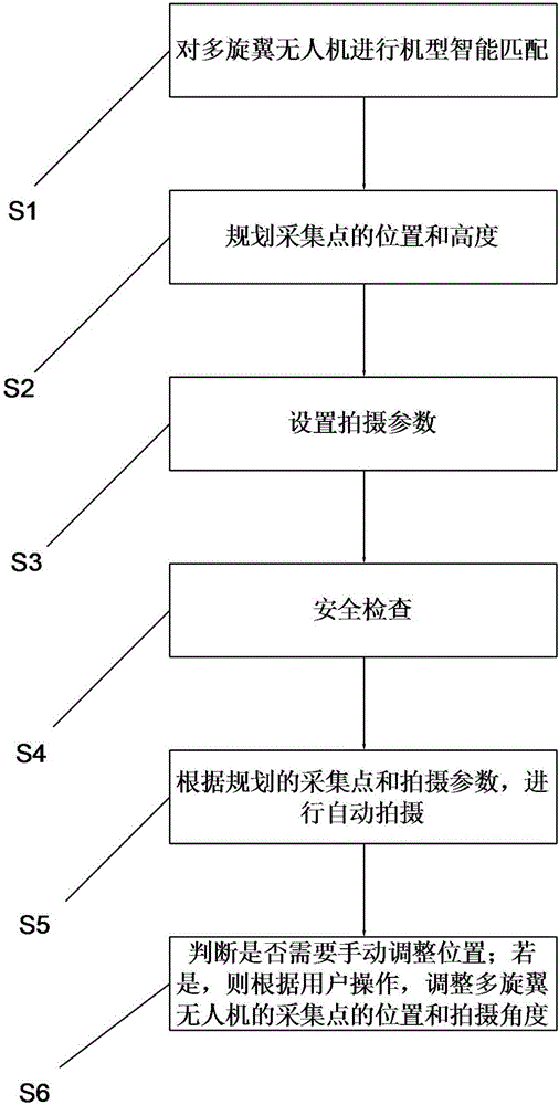
[0061] In order to solve the technical defect in the prior art that manual operation is required when collecting aerial panoramic data, the present invention provides a system and method for aerial panoramic data collection. Introduce specifically through the following embodiments.

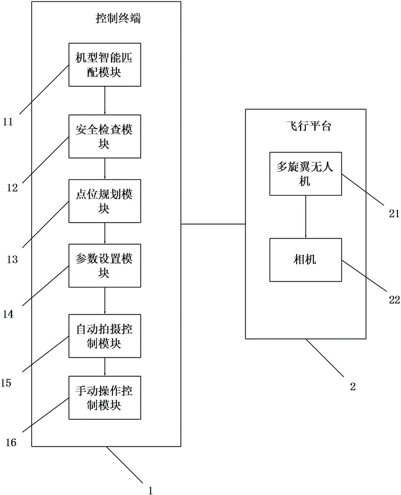
[0062] see figure 1 , which is a connection block diagram of the air panorama data acquisition system of the present invention. The present invention provides an aerial panorama data collection system, which includes a control terminal 1 and a flight platform 2 .

[0063] The flying platform 2 includes a multi-rotor UAV 21 and a camera 22 mounted on the multi-rotor UAV.

[0064] The control terminal 1 includes: a model intelligent matching module 11 , a point planning module 12 , a parameter setting module 13 , a safety inspection module 14 , an automatic shooting control module 15 and a manual operation control module 16 .

[0065] The model intelligent matching module 11 is used for intelligent...


PUM


Abstract

The invention relates to a full-automatic air panoramic data collection system. The system comprises a control terminal and a flying platform, wherein the flying platform comprises a multi-rotor unmanned aerial vehicle (UAV) and a camera mounted on the multi-rotor UAV; the control terminal comprises a point location planning module used for planning the location and the height of a collection point, and a parameter setting module used for setting a horizontal spacing angle and a vertical inclination angle; the multi-rotor UAV carries out positioning and shooting angle adjustments according to the planned collection point and set parameters; and the camera is used for shooting when the multi-rotor UAV is located at the set collection point and the set shooting angles. Compared with the prior art, the system and the control terminal provided by the invention have the advantages that automatic shooting is achieved, and manual operations are not required, so that the accuracy is high.

Description

technical field [0001] The invention relates to the field of unmanned aerial vehicle control, in particular to a fully automatic aerial panorama data acquisition system, method and control terminal. Background technique [0002] The ground 360 panorama started five years ago, and the shooting equipment has developed from a simple single-lens, manual pan-tilt to a variety of fully automatic camera equipment. Of course, the cost has also doubled and increased dozens of times. The operation process has reached the current fully automatic shooting from the initial manual operation. Now it has been applied to many industries such as street view, tourist attractions, hotels, real estate, etc., and has become an important content production method of virtual reality. [0003] The aerial 360 panorama has developed rapidly with the development of consumer-grade multi-rotor drones in the past two years. At present, it is mainly for aviation enthusiasts to shoot some interesting land...

Claims


Application Information

Patent Timeline
Patent Type & Authority Applications(China)
IPC IPC(8): H04N5/232G05D1/02G05D1/04G05D1/08
CPCG05D1/0202G05D1/042G05D1/0808H04N23/617H04N23/698
Inventor 罗志勇熊勇良
Owner 广州优飞信息科技有限公司
Why Eureka
Try Eureka