Fluorescence-detected assays on microfluidic chips

A microfluidic chip, fluorescence detection technology, applied in fluorescence/phosphorescence, measurement devices, laboratory utensils, etc., can solve the problems of increasing the total cost of the system, disadvantages, and differentiation of signal parts.

Active Publication Date: 2016-12-14
ONE DROP DIAGNOSTICS
View PDF21 Cites 9 Cited by
  • Summary
  • Abstract
  • Description
  • Claims
  • Application Information

AI Technical Summary

Problems solved by technology

The use of very high quality filters may become necessary to achieve acceptable S / N, thus increasing the overall cost of the system
Third, the presence of excitation light outside the detection region can be detrimental to S / N by generating parasitic fluorescence emission
[0063] The second major disadvantage comes from the fact that the waveguide is interrupted by the microfluidic channel
It also inhibits the use of such systems for multiplexed applications, since any different assay regions couple their fluorescent signals into the same waveguide layer, making it impossible to distinguish some signal fractions from each other

Method used


Image

  • Fluorescence-detected assays on microfluidic chips
  • Fluorescence-detected assays on microfluidic chips
  • Fluorescence-detected assays on microfluidic chips

Examples


Embodiment Construction

[0114] The examples provided hereinafter provide improved illustrations of the invention, but are not intended to limit the invention to the features disclosed herein. Components that are identical or at least functionally identical are identified below with identical or at least corresponding reference numerals.

[0115]The invention will be described using a fluorescence detection immunoassay as an example of a fluorescence detection assay test. However, as is clear to a person skilled in the art, the invention can be implemented by any other fluorescence detection assay technique in which the fluorophore is immobilized on the surface either permanently or at some stage of the assay process. Accordingly, the described embodiment of a fluorescence detection immunoassay on a microfluidic chip will represent an illustrative example only and is not intended to limit the invention to this particular type of assay.

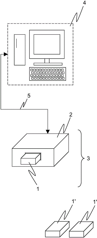
[0116] exist figure 1 An exemplary embodiment of a diagnostic ...


PUM

PropertyMeasurementUnit
refractive indexaaaaaaaaaa

Abstract

An assay unit for carrying-out fluorescence-detected assays on one or more physiological samples, comprises a microfluidic chip with a microfluidic system that is able to convey a physiological sample or analyte solution through one or more microfluidic channels (30) arranged on the chip, and a photonic system with two or more rectangular waveguide structures (62, 66, 63) arranged on the chip that are able to guide excitation light (64, 65) in the near IR, visible, or near UV range. The one or more microfluidic channels and the two or more waveguide structures cross each other at a detection site (26). In an assay area (32), where a certain microfluidic channel and a certain waveguide structure cross each other, one or more lateral surfaces of the core of the waveguide structure (66) at least partially face the inner volume of the microfluidic channel, such that an evanescent field of light guided the waveguide structure overlaps with a certain part of the inner volume of the microfluidic channel. In the assay areas (32) one or more capture spots are located on the surface of the waveguide core, the capture spots comprising a coating of capture antibodies of the immunoassay, immobilized on said core surface.

Description

technical field [0001] The invention relates to an assay unit for performing a fluorescence detection assay, a reader unit for reading the results of this assay unit and a diagnostic device with such an assay unit and reader unit according to the preambles of the independent claims . Background technique [0002] Physiological samples such as body fluids may be analyzed for various biochemical analyses. Accurate medical diagnosis is an important part of medical treatment, such as identification, monitoring, prognosis and companion diagnosis of health conditions and diseases. There are two main contexts in which medical diagnostic systems are used: dedicated medical laboratories and so-called point-of-care (POC) testing. [0003] The term "physiological sample" in the context of this specification shall include all materials that are biological material such as blood, urine, stool or tissue taken from a patient or samples prepared for subsequent analysis based on such biolo...

Claims


Application Information

Patent Timeline
Patent Type & Authority Applications(China)
IPC IPC(8): G01N21/64G01N21/77B01L3/00
CPCB01L3/502715G01N21/7703G01N21/7746G01N2021/6439G01N2021/7736G01N2021/7786B01L2300/0654B01L2300/0816B01L2300/0877B01L2300/0887G01N21/648B01L2300/0627G01N21/6428G01N33/54306G01N2201/08
Inventor L·吉瓦斯J·齐格勒N·迪斯哈尔梅斯
Owner ONE DROP DIAGNOSTICS
Why Eureka
Try Eureka