
Plate drying room

A drying chamber and plate technology, which is applied in the fields of pretreatment of surfaces, coatings, and devices for coating liquids on surfaces, etc., can solve the problems of difficulty in matching the rhythm of the drying time of the production line, the quality of the coating cannot be guaranteed, and the space occupied is large. The effect of speeding up the drying speed, speeding up the drying of the paint surface and saving electricity

Inactive Publication Date: 2016-12-21
金乡县元顺农贸有限公司
View PDF0 Cites 0 Cited by
  • Summary
  • Abstract
  • Description
  • Claims
  • Application Information

AI Technical Summary

Problems solved by technology

[0002] With the continuous improvement of the paint drying time, quality and environmental protection requirements in the woodworking fixture industry, the quality of the coating under the conditions of manual spraying and natural drying cannot be guaranteed, and the handling of materials, placement space, and air dryness during the drying process The degree, drying time, batch size, connection between upper and lower processes, etc. are not compatible with the entire production line; although there are already horizontal upwind dryers and other drying equipment, they still occupy too much space, the production line is too long, and the drying time and the rhythm of the production line are not easy matching

Method used


Image

  • Plate drying room

Examples


Embodiment

[0012] The present invention will be further described below in conjunction with the accompanying drawings.

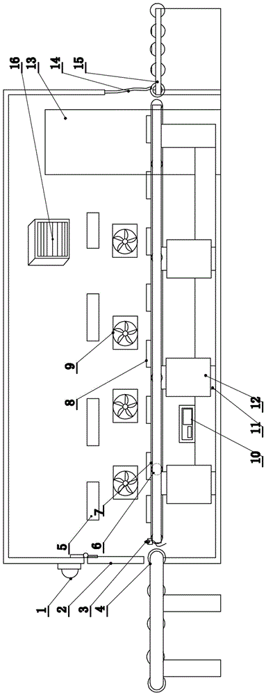
[0013] The panel drying room consists of a drying room with conveyor belts running along the length of the drying room and running through the room. There are inlets and outlets on the side plates opposite to the two ends of the conveyor belt in the drying room. The outer sides of the entrance and the outlet are respectively provided with a warehouse-in support and a warehouse-out support 15, and some rollers 4 are distributed on the warehouse-out support 15. Roller 4 is consistent with conveyer belt height.

[0014] A plurality of heating plates 12 are distributed on the legs 11 of the conveyor belt or on the wall of the drying room. The heating plates 12 and the temperature sensor are connected to the electrical control box 10, and the heating plates 12 are connected to a constant temperature controller to make the interior of the room dry at a constant temperature....


PUM


Abstract

The invention discloses a plate drying room and provides a drying device which is high in heat utilization rate, fast in drying speed, stable in quality and high in air dryness and cleanness, and used for improving the quality of a paint drying process. The plate drying room is characterized by comprising a drying room with a transmission belt; an inlet and an outlet are formed in side walls, opposite to two ends of the transmission belt, of the drying room; a storage bracket and a delivery bracket are respectively arranged on the outer sides of the inlet and the outlet; a plurality of heating plates are distributed on support legs of the transmission belt or walls of the drying room; the heating plates and a temperature sensor are connected with an electric control box; a plurality of fans are mounted in the drying room, and are connected with the electrical control box; a plurality of rectangular observation windows are distributed on the wall on one side, in the length direction, of the drying room; and a dehumidifier with an automatic dehumidifying function is arranged in the drying room. As the heating plates are distributed in the heating room, the dryness and the temperature of the drying room can be kept constant; and as the fans are mounted in the drying room, hot air can diffuse uniformly.

Description

technical field [0001] The invention relates to a drying device for drying paint with high heat utilization rate, fast drying speed and stable quality. Background technique [0002] With the continuous improvement of the paint drying time, quality and environmental protection requirements in the woodworking fixture industry, the quality of the coating under the conditions of manual spraying and natural drying cannot be guaranteed, and the handling of materials, placement space, and air dryness during the drying process The degree, drying time, batch size, connection between upper and lower processes, etc. are not compatible with the entire production line; although there are already horizontal upwind dryers and other drying equipment, they still occupy too much space, the production line is too long, and the drying time and the rhythm of the production line are not easy matching etc. The above-mentioned problems are especially obvious under the conditions of using automatic...

Claims


Application Information

Patent Timeline
Patent Type & Authority Applications(China)
IPC IPC(8): B05D3/04B05D3/02
CPCB05D3/0413B05D3/0254B05D2203/20
Inventor 周生勤肖德生张向东
Owner 金乡县元顺农贸有限公司
Learn More