Rebar feed reinforcement clamping device

A clamping device and feeding technology, applied in the field of machining, can solve problems such as poor applicability, and achieve the effects of strong applicability, good reliability and long service life

Inactive Publication Date: 2016-12-21
ZHEJIANG WILLING TECH
View PDF7 Cites 6 Cited by
  • Summary
  • Abstract
  • Description
  • Claims
  • Application Information

AI Technical Summary

Problems solved by technology

During the feeding process of steel bars, it is necessary to clamp the steel bars. Generally, a large clamping force is required in the process

Method used


Image

  • Rebar feed reinforcement clamping device

Examples


Embodiment Construction

[0011] The present invention will be further described in detail below in conjunction with the accompanying drawings and examples. The following examples are explanations of the present invention and the present invention is not limited to the following examples.

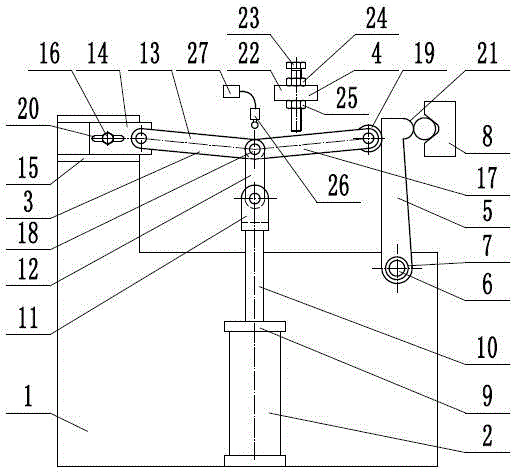
[0012] Such as figure 1 Shown, a kind of reinforcement clamping device of feeding force, it comprises frame 1, cylinder 2, connecting rod mechanism 3, limit mechanism 4, pressure rod 5, pressure rod pin shaft 6, return torsion spring 7, workpiece Support base 8, described cylinder 2 comprises cylinder body 9, piston rod 10, connecting lug 11, and described cylinder body 9 is fixed on the frame 1, and one end of described piston rod 10 is provided with connecting lug 11, and described Link mechanism 3 comprises supporting link 12, rocking bar 13, rocking bar support plate 14, guide rail 15, fastening screw 16, first connecting rod 17, bearing pin 18, pressure roller 19, and described rocking bar support plate 14 can ...


PUM


Abstract

The invention provides a rebar feed reinforcement clamping device and belongs to the technical field of machining. The rebar feed reinforcement clamping device comprises a connection rod mechanism and a limiting mechanism. A rocker support plate of the connection rod mechanism is provided with a U-shaped groove and is installed on a rack through a fastening screw. The left end of a rocker is hinged to the rocker support plate. The lower end of a bearing connection rod is hinged to a connection support lug. The upper end of the bearing connection rod, the right end of the rocker and the left end of a first connection rod are hinged through hinge pins. A pressing wheel is rotationally arranged at the right end of the first connection rod. The lower end of a pressing rod is hinged to the rack through a pressing rod hinge pin and is further provided with a return torsional spring. The upper end of the pressing rod is attached to the pressing wheel tightly. The limiting mechanism is arranged above the first connection rod. According to the rebar feed reinforcement clamping device, the reinforcement characteristic of the connection rod mechanism near a dead center position is utilized, very large clamping force is generated to a rebar through small cylinder thrust, the rebar feed reinforcement clamping device can be suitable for clamping of various models of rebars, and thus the applicability is high.

Description

technical field [0001] The invention relates to the technical field of mechanical processing, in particular to a reinforcing bar feeding clamping device. Background technique [0002] Machining refers to the process of changing the shape or performance of a workpiece through a mechanical device. According to the difference in processing method, it can be divided into cutting processing and pressure processing. In the production process, the process of changing the shape, size, position and nature of the production object to make it a finished or semi-finished product is called a process. It is an essential part of the production process. The process can be divided into casting, forging, stamping, welding, machining, assembly and other processes. The mechanical manufacturing process generally refers to the sum of the machining process of parts and the assembly process of machines. Other processes are called auxiliary processes. Processes, such as transportation, storage, p...

Claims


Application Information

Patent Timeline
IPC IPC(8): B23Q3/08
CPCB23Q3/08
Inventor 蒋文星杨桂灿黄国荣
Owner ZHEJIANG WILLING TECH
Why Eureka
Try Eureka