Optical module automatic chip mounting and assembling machine

An optical component, automatic patch technology, applied in the direction of optical components, connecting components, mechanical equipment, etc., can solve the problems of slow efficiency, difficult to control product position positioning, poor stability and consistency, etc., to improve product quality, improve Accuracy and the effect of improving production efficiency

Inactive Publication Date: 2016-12-21
OPTIMAL COATECH GUANGZHOU CO LTD
View PDF3 Cites 42 Cited by
  • Summary
  • Abstract
  • Description
  • Claims
  • Application Information

AI Technical Summary

Problems solved by technology

The existing technology is mainly manual patching operation under a microscope. It is difficult to control the uniformity and amount of UV glue, as well as the positioning of the product, so the product stability and consistency are relatively poor, and the efficiency is relatively slow.

Method used


Image

  • Optical module automatic chip mounting and assembling machine
  • Optical module automatic chip mounting and assembling machine
  • Optical module automatic chip mounting and assembling machine

Examples


Embodiment Construction

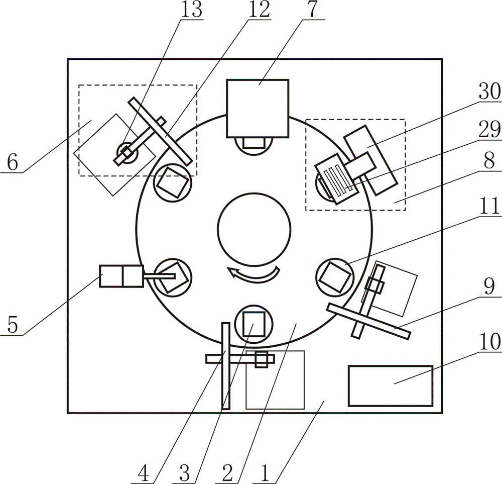
[0017] Such as figure 1 As shown, the automatic patch assembly machine for optical components includes a workbench 1 and an intermittent turntable 2 arranged on the workbench 1. On the intermittent turntable 2, there are six jigs 3 evenly distributed along its periphery. A glass prism feeding manipulator 4, a dispensing device 5, a filter feeding device 6, a patch pressing device 7, UV curing device 8, finished product take-out manipulator 9 and controller 10; under the control of controller 10, glass prism feeding manipulator 4 puts the glass prism into the fixture 3 on the intermittent turntable 2, and the intermittent turntable 2 rotates One station, the glass prism in the tooling fixture 3 is transferred to the dispensing station, the glue dispensing device 5 injects glue onto the glass prism in the tooling fixture 3, the intermittent turntable 2 rotates a station, and the glue in the tooling fixture 3 The glass prism is transferred to the filter feeding station. The filt...


PUM


Abstract

The invention discloses an optical module automatic chip mounting and assembling machine. The optical module automatic chip mounting and assembling machine comprises a worktable and an intermittent rotary plate arranged on the worktable. Six tool clamps are evenly distributed along the periphery of the intermittent rotary plate at intervals. A glass prism feeding manipulator, a glue dispensing device, an optical filter feeding device, a chip mounting press-fitting device, a UV curing device, a finished product taking manipulator and a controller which correspond to the tool clamps are sequentially arranged on the worktable and around the intermittent rotary plate. Linkage of all the processes is realized through the intermittent rotary plate with six stations, glass prism feeding, glue dispensing, optical filter feeding, chip mounting press-fitting, UV curing and finished product taking are carried out in sequence, and automatic operation of all the procedures is realized. Automatic batch production is realized through various sensors and electric element control machines and mechanisms, and the production efficiency, and reliability and consistency of novel products are improved. As the glue outlet amount can be controlled accurately, the accuracy of chip mounting and assembling is greatly improved, and product quality is improved.

Description

technical field [0001] The invention relates to an automatic production equipment in the field of optical communication, in particular to an automatic patch assembly machine for optical components. Background technique [0002] In the field of optical communication, with the development of technologies and markets such as 4G / 5G, FTTH deployment, high-speed optical transmission, and optical access, the growth of the optical communication market is being driven. Optical communication technology is developing in the direction of integration and intelligence. With the advancement of Industry 4.0, optical communication automation production will become the only way for the development of enterprises, which will bring about huge changes in enterprise management, quality control, and consistency of product performance. [0003] The existing technology is to manually mount odemux optical components, work under a microscope, and use corresponding fixtures to assemble the filter and ...

Claims


Application Information

Patent Timeline
Patent Type & Authority Applications(China)
IPC IPC(8): B29C65/48F16B11/00B29C65/80B29L11/00
CPCB29C65/48B29C65/80B29L2011/0016F16B11/006
Inventor 朱伟杰
Owner OPTIMAL COATECH GUANGZHOU CO LTD
Why Eureka
Try Eureka