Eureka AIR delivers breakthrough ideas for toughest innovation challenges, trusted by R&D personnel around the world.

Pinion-and-rack type elevator under balanced drive

A driving gear and rack type technology, applied in the field of elevators, can solve problems such as unbalanced force on the elevator car, self-heavy elevator car, and complex transmission system

Inactive Publication Date: 2016-12-21
廖忠民
View PDF9 Cites 4 Cited by
  • Summary
  • Abstract
  • Description
  • Claims
  • Application Information

AI Technical Summary

Problems solved by technology

[0002] Some existing rack-and-pinion elevators have their own advantages, but there are also some points for improvement, including, some schemes are single-sided drive, so the elevator car is subjected to a single-sided driving force, and the load transported by the elevator car The distribution is random. For example, when a freight elevator carries items with a large specific gravity or transports goods with a trolley, the load will be concentrated on a small area at the bottom of the car, so that the car bears the concentrated load. If these concentrated loads are distributed If the weight is on the side with the driving force, then the driving force and the direction of the load should correspond. If the distribution is uniform, although the driving force and the direction of the load are somewhat offset, the negative impact is not too great. side, the force on the elevator car will be severely unbalanced, which will become a serious hidden danger to safe and stable operation; it is impossible for ordinary users to know whether the driving force of the elevator car is balanced or biased to one side, and the instructions for use can generally only be It is required that when using the elevator, the goods should be placed in the middle of the car and avoid concentrated loads, but in some cases it is impossible to do so, for example, when the trailer enters and exits the car, the car will be subjected to a large gravity force Function, after the trailer enters the car, it does not necessarily stop in the middle of the car, resulting in heavy loads, etc.; but if non-single-sided drive is used, the transmission system is more complicated and heavy. Symmetrical drive scheme), some include multi-stage transmission, and some have manual devices, including handwheels or handles, gear transmission systems, turning clutches, and electric motors, which make the elevator car heavy and increase energy consumption , which reduces the effective transport capacity; therefore, how to achieve stable operation and light weight of the elevator car is an important part of the improvement of the rack and pinion elevator

Method used


Image

  • Pinion-and-rack type elevator under balanced drive
  • Pinion-and-rack type elevator under balanced drive
  • Pinion-and-rack type elevator under balanced drive

Examples


Embodiment 1

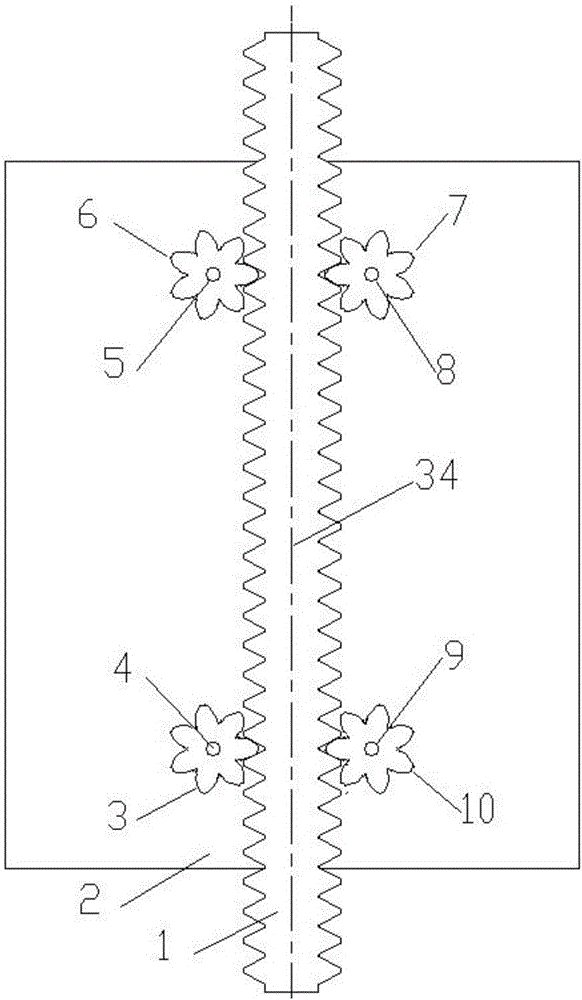
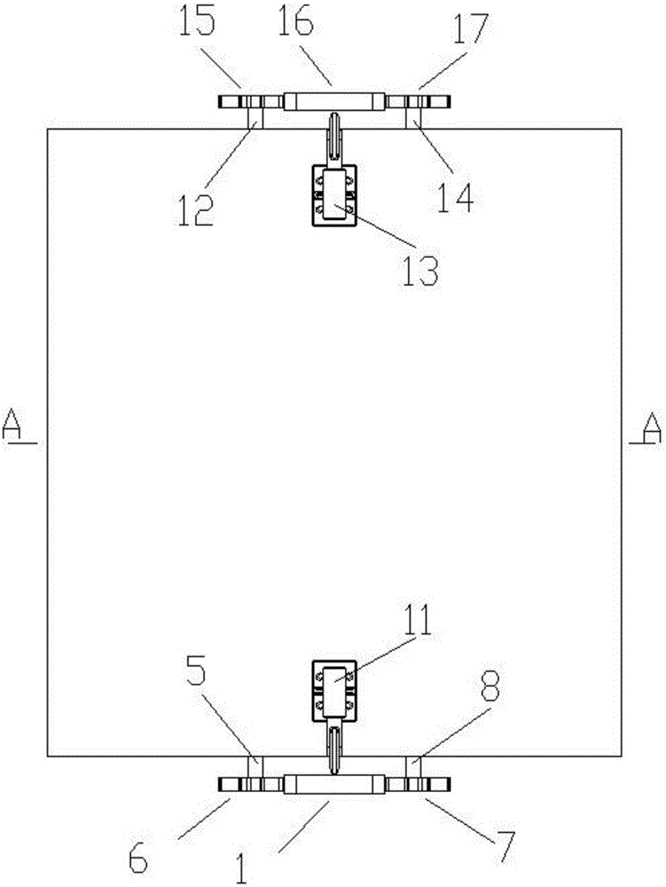
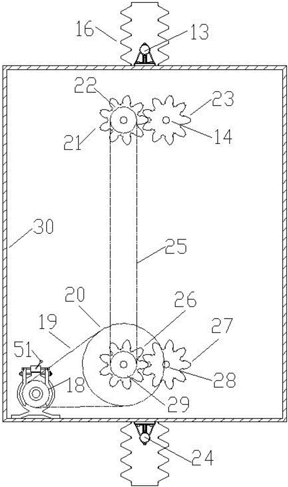
[0018] Embodiment 1, with Figure 1~4 It is also the accompanying drawing of embodiment 1, and the description of the composition and function of each part of its structure is shown in [0005] and [0006]. Since it involves the coordination of multiple transmission systems, special attention should be paid to manufacturing The quality and installation quality must ensure the necessary accuracy, and the trial operation can only be carried out after passing the test. The test includes ultrasonic flaw detection of the driving gear and rack materials, and the verticality of the guide rail is measured by a laser elevator guide rail verticality measuring instrument; Its electrical control system uses an embedded system as the main control system, and the "power-off star connection" unit circuit and the attached Figure 5 And [0007] the same as described in the paragraph; its work process is mainly, when the system has no electricity, including disconnecting the power switch or unexpec...

Embodiment 2

[0019] Embodiment 2, with Figure 1~2 Also applicable to Embodiment 2, the description of the composition and function of each part of its structure is described in [0005] and [0006]. Since it involves the coordination of multiple transmission systems, special attention should be paid to the quality of manufacture and The installation quality must ensure the necessary accuracy, and the test run can only be carried out after passing the test. The test includes ultrasonic flaw detection of the driving gear and rack materials, and the verticality of the guide rail is measured by a laser elevator guide rail verticality measuring instrument; its electrical The control system uses an embedded system as the main control system, and the "power-off star connection" unit circuit and the attached Figure 5 And [0007] paragraph described same, its work process is also roughly the same with embodiment 1; Its transmission system has been changed in the scope of the basic ideas of the claims...


PUM


Abstract

The invention discloses a pinion-and-rack type elevator under balanced drive. The pinion-and-rack type elevator is characterized in that a driving system is a balanced driving system; an active force transmission system is a synchronous belt transmission system; an electric traction system is a permanent magnet direct current motor system or a permanent magnet alternating current synchronous motor system; a lower right driving drive gear and a lower right driven drive gear are engaged with a right rack which is fixed in the vertical direction from the back and the front of the lower portion, an upper right driving drive gear and an upper right driven drive gear are engaged with the right rack which is fixed in the vertical direction from the back and the front of the upper portion, a lower left driving drive gear and a lower left driven drive gear are engaged with a left rack which is fixed in the vertical direction from the back and the front of the lower portion, and an upper left driving drive gear and an upper left driven drive gear are engaged with the left rack which is fixed in the vertical direction from the back and the front of the upper portion, so that a lift car system of the elevator is driven to ascend or descend; a brake wheel, coaxial with a motor shaft, of the elevator is configured with a double-backup power-losing braking brake; and an electric control system is internally provided with a 'power failure star connection' unit circuit which is electrically interlocked and mechanically interlocked.

Description

technical field [0001] The invention relates to the field of elevators, in particular to a rack and pinion elevator. Background technique [0002] Some existing rack-and-pinion elevators have their own advantages, but there are also some points for improvement, including, some schemes are single-sided drive, so the elevator car is subjected to a single-sided driving force, and the load transported by the elevator car The distribution is random. For example, when a freight elevator carries items with a large specific gravity or transports goods with a trolley, the load will be concentrated on a small area at the bottom of the car, so that the car bears the concentrated load. If these concentrated loads are distributed If the weight is on the side with the driving force, then the driving force and the direction of the load should correspond. If the distribution is uniform, although the driving force and the direction of the load are somewhat offset, the negative impact is not ...

Claims


Application Information

Patent Timeline
Patent Type & Authority Applications(China)
IPC IPC(8): B66B11/04B66B5/04
CPCB66B11/0461B66B5/044
Inventor 廖忠民
Owner 廖忠民
Why Eureka
Eureka Blog
Learn More