A tie-rod composite spring-damper with preset early stiffness

A composite spring and damper technology, applied in the direction of spring/shock absorber, spring/shock absorber functional characteristics, spring, etc. The effect of isolation cost

Active Publication Date: 2018-03-27
宿州市徽腾知识产权咨询有限公司
View PDF8 Cites 0 Cited by
  • Summary
  • Abstract
  • Description
  • Claims
  • Application Information

AI Technical Summary

Problems solved by technology

However, this utility model patent obviously has the following disadvantages: 1. Two coil springs are required, and the length of the entire damper is relatively long, which is not suitable for installation in a space with a small distance; 2. It is difficult or even impossible to ensure the two springs in the process Only the stiffness of the spring (including tensile stiffness and compression stiffness) is equal, so the shock absorption effect is different in different wind directions; 3. The initial stiffness of the damper cannot be changed to achieve the preset wind resistance level and reduce the cost of shock absorption; 4. A helical spring works in two states of tension and compression at the same time. The metal material and production process of the existing spring are difficult to meet the requirements. The two working states of tension and compression can only be realized by reducing the elastic deformation range of the helical spring. , which obviously wastes resources
The above three means of changing the effective working length of the spring are obviously not suitable for composite springs; in addition, this type of anti-shock absorber not only shortens the effective working length of the spring, but also can only compress energy and reduce vibration, and cannot stretch energy. Vibration reduction

Method used


Image

  • A tie-rod composite spring-damper with preset early stiffness
  • A tie-rod composite spring-damper with preset early stiffness
  • A tie-rod composite spring-damper with preset early stiffness

Examples


example 1

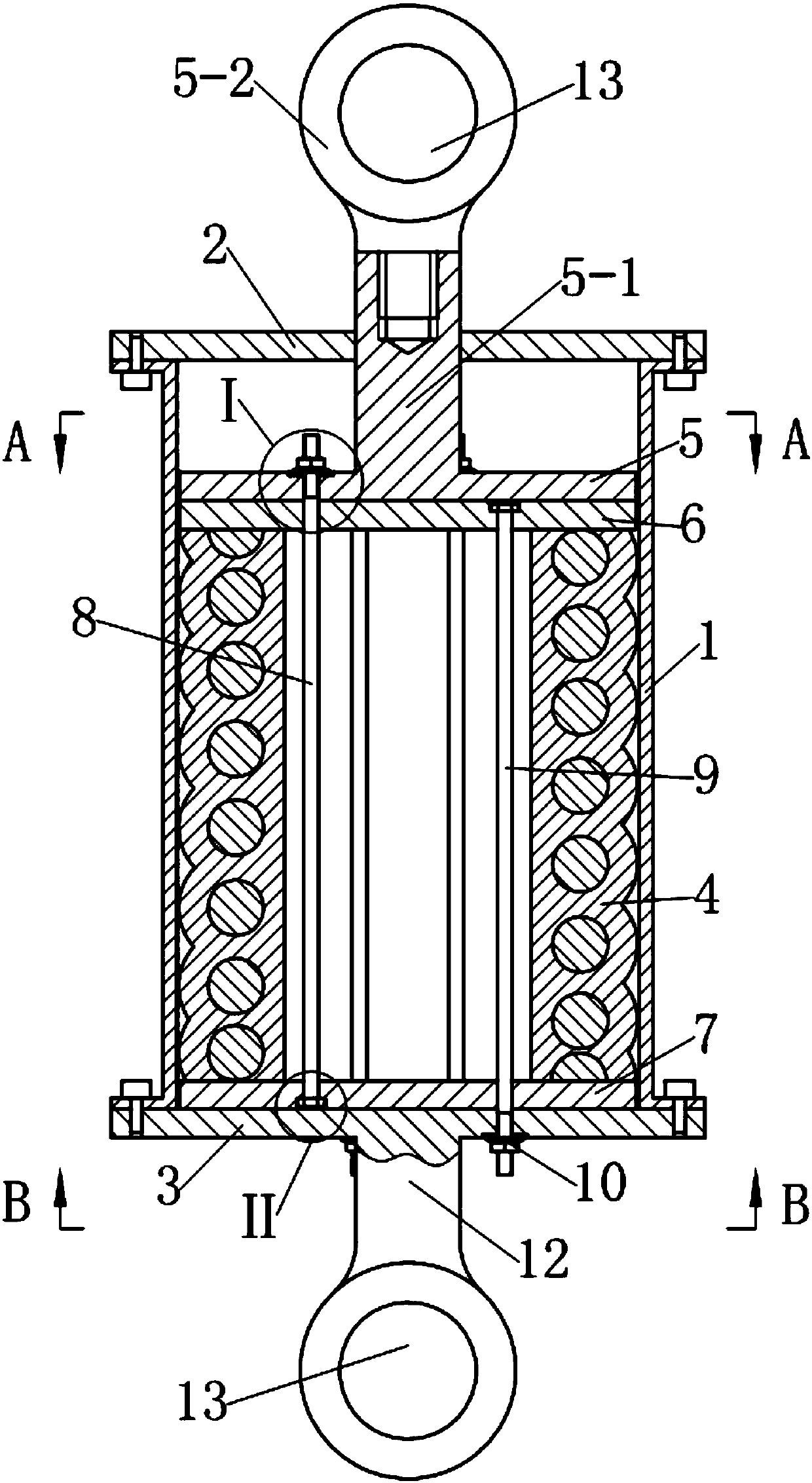
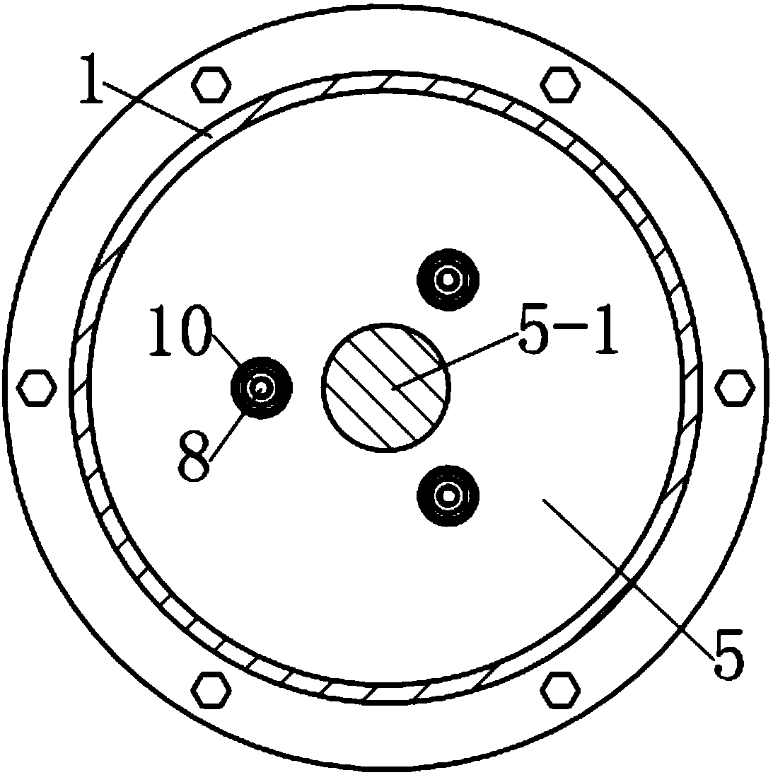
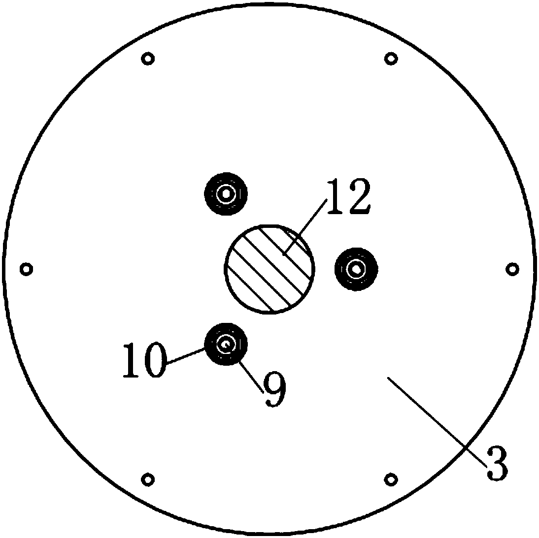
[0026] see figure 1 , the tie-rod composite spring damper with preset early stiffness in this example is an energy-dissipating device that can be used for seismic reinforcement of building structures. 2 and the second end cover 3, wherein, the first end cover 2 and the second end cover 3 are respectively fixedly connected to the two ends of the guide sleeve by screws. A composite spring 4 (compounded by cylindrical metal helical compression spring and rubber material) is provided in the guide sleeve 1 along the axial direction, and a driving member extends into the guide sleeve 1 from the center of the first end cover 2 ; Wherein, the driving member is composed of a dynamic pressure plate 5 located at the upper end of the composite spring 4 and movingly matched with the guide sleeve 1, and a driving rod 5-1 extending upward from the upper surface of the dynamic pressure plate 5 out of the guide sleeve 1, the driving rod The end of 5-1 located outside the guide sleeve 1 is pr...

example 2

[0035] see Figure 6-8 , the tie-rod composite spring damper with preset early stiffness in this example is a kind of vibration isolation device (also called seismic isolation support) that can be used for vertical vibration isolation of buildings. Compared with Example 1, this example mainly has The difference is as follows:

[0036] 1. As a vibration isolation support, in order to facilitate installation, the connecting rod provided on the second end cover 3 in Example 1 is omitted in this example, and the second end cover 3 is extended axially downward from the edge and then outward It extends radially, and is evenly provided with connecting bolt holes 15 at the edge. The second end cover 3 is used as the base of the shock-isolation support, and the length of the downward axial extension needs to be greater than that of the second group of polished rod bolts 9. The length of the outer portion of the second end cap 3 . The driving rod 5-1 of the driving member is a metal t...


PUM


Abstract

The invention discloses a pull rod type composite spring damper with the early stiffness capable of being preset. The pull rod type composite spring damper is characterized in that a counter pressure device is further arranged in a guide sleeve and comprises two sets of prepressing pull rods and two floating pressing plates; one of the two floating pressing plates is arranged between a movable pressing plate and a composite spring, and the other floating pressing plate is arranged between a second end cover and the composite spring; the two sets of prepressing pull rods are distributed in a center hole of the composite spring; for one set of the two sets of prepressing pull rods, one ends are fixed to the floating pressing plate adjacent to the movable pressing plate, and the other ends penetrate through the floating pressing plate adjacent to the second end cover and the second end cover and are fixed to a limiting element; and for the other set of prepressing pull rods, one ends are fixed to the floating pressing plate adjacent to the second end cover, and the other ends penetrate through the floating pressing plate adjacent to the movable pressing plate and the movable pressing plate and are fixed to a limiting element.

Description

technical field [0001] The present invention relates to a shock absorbing device, in particular to a damper using a composite spring. Background technique [0002] The full name of the composite spring is rubber-metal helical composite spring, which is a kind of spring formed by wrapping a layer of rubber material around the metal helical spring and compounding vulcanization. The composite spring has the nonlinear characteristics of the rubber spring, and has the characteristics of large deformation and large load-bearing capacity of the metal coil spring, and its stability and load-bearing capacity are better than those of the rubber spring. Because the composite spring has a working characteristic curve similar to that of a rubber air spring, but is simpler in structure than a rubber air spring, and has no risk of gas leakage, it is also used to replace the rubber air spring and is widely used in mining, metallurgy, coal and other large vibration equipment. It can reduce ...

Claims


Application Information

Patent Timeline
Patent Type & Authority Patents(China)
IPC IPC(8): F16F3/12F16F7/00
CPCF16F3/12F16F7/00F16F2228/066
Inventor 沈珊胡济福胡济全
Owner 宿州市徽腾知识产权咨询有限公司
Why Eureka
Try Eureka