Air distribution system for biomass boiler and fuzzy control method

A biomass boiler and air distribution system technology, applied in the combustion method, combustion control, air supply adjustment and other directions, can solve the problems of high emission concentration, low biomass combustion efficiency, poor air distribution effect, etc., to improve work efficiency , to ensure the effect of full combustion

Active Publication Date: 2016-12-21
JILIN ELECTRIC POWER RES INST LTD
View PDF5 Cites 2 Cited by
  • Summary
  • Abstract
  • Description
  • Claims
  • Application Information

AI Technical Summary

Problems solved by technology

[0002] At present, coal is still the main fuel for heating in major cities in northern my country, which not only consumes a large amount of coal resources every year, but also causes serious environmental pollution.
Biomass fuel has the characteristics of low cost and "zero emission". At present, the formula system of biomass boilers blows air from bottom to top (that is, there is only one blowing passage), which leads to poor air distribution effect, large resistance of flue gas along the way, and The material combustion efficiency is low, which leads to high emission concentrations of CO and NO in the flue gas. Therefore, the research and development of heating boilers fueled by biomass has important economic and environmental significance.

Method used


Image

  • Air distribution system for biomass boiler and fuzzy control method
  • Air distribution system for biomass boiler and fuzzy control method
  • Air distribution system for biomass boiler and fuzzy control method

Examples


Embodiment Construction

[0036] The present invention will be further described in detail below in conjunction with the accompanying drawings, so that those skilled in the art can implement it with reference to the description.

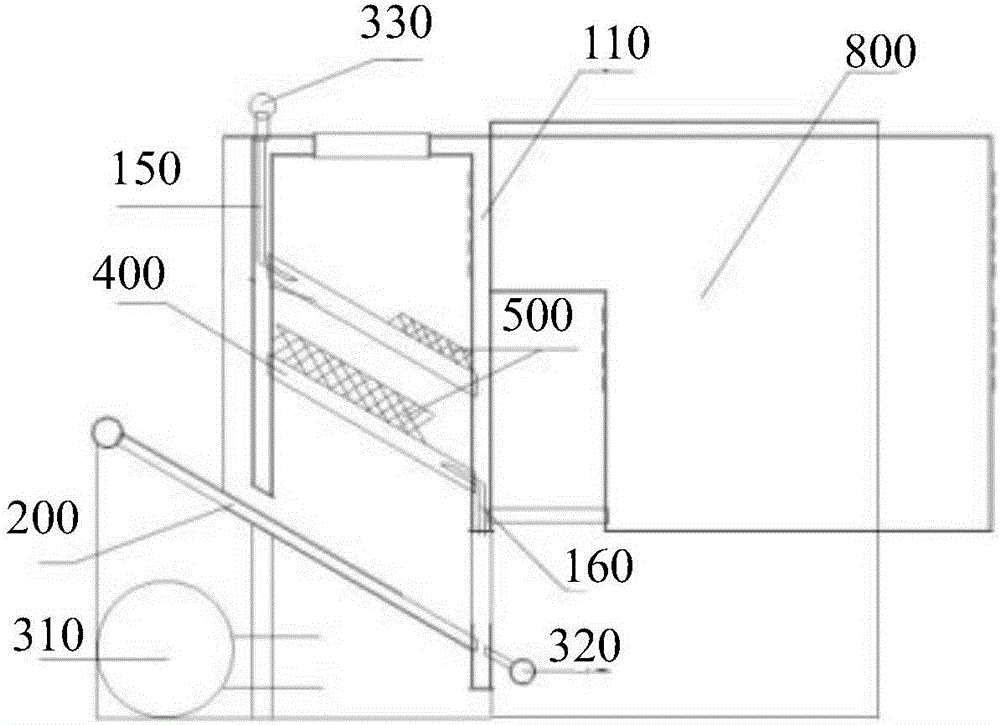
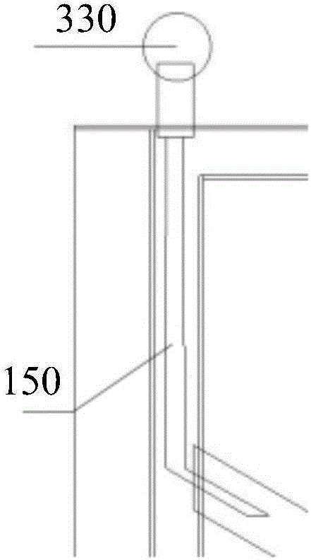
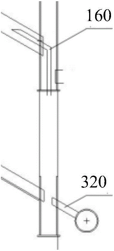
[0037] Such as figure 1 As shown, the air distribution system for a biomass boiler provided by the present invention includes: a combustion chamber 100 , a left air duct 150 , a right air duct 160 , a fire grate 200 , a combustion chamber drain 400 and a water storage tank 800 .

[0038] Wherein, water wall 110 is arranged on the two side walls of combustion chamber 100, which is used for water circulation in the boiler; air duct, which includes left air duct 150 and right air duct 160, wherein left air duct 150 is connected to the top of left water wall, and right air duct The duct 160 is connected to the bottom of the water wall on the right, and the air duct has an air outlet, which is located at the top of the left air duct and the right air duct, parallel to the horizont...


PUM


Abstract

The invention discloses an air distribution system for a biomass boiler. The air distribution system comprises a combustion chamber, a water wall, air flues, a fire grate, a first air blower, a second air blower and a third air blower. The water wall is mounted on the side wall of the combustion chamber. The air flues comprise the left air flue and the right air flue, penetrate through the inside of the water wall and are oppositely arranged on the two sides of the combustion chamber. The fire grate is obliquely arranged at the bottom of the combustion chamber, and the fire grate and the lower space of the combustion chamber form an air bin. The first air blower is arranged in the air bin and is used for feeding primary air to the combustion chamber from bottom to top. The second air blower is arranged at the bottom of the right air flue and used for feeding secondary air to the middle of the combustion chamber through the air flue on the right side. The third air blower is arranged on the top of the left air flue and used for feeding tertiary air to the upper portion of the combustion chamber through the air flue on the left side. The secondary air and the tertiary air are reasonably distributed to enable biomass fuel and air to make fully contact. The invention further discloses a fully control method for air distribution of the biomass boiler. Evaluation factors are calculated and input into a fuzzy controller, the air speed of the air blowers is controlled precisely, fully combustion of the fuel is guaranteed, and the working efficiency of the boiler is improved.

Description

technical field [0001] The invention relates to a boiler system, in particular to an air distribution system for a biomass boiler and a fuzzy control method for air distribution for a biomass boiler. Background technique [0002] At present, coal is still used as the main fuel for heating in major cities in northern my country, which not only consumes a large amount of coal resources every year, but also causes serious environmental pollution. Biomass fuel has the characteristics of low cost and "zero emission". At present, the formula system of biomass boilers blows air from bottom to top (that is, there is only one blowing passage), which leads to poor air distribution effect, large resistance of flue gas along the way, and The low combustion efficiency of substances leads to high emission concentrations of CO and NO in the flue gas. Therefore, the research and development of heating boilers fueled by biomass has important economic and environmental significance. Content...

Claims


Application Information

Patent Timeline
Patent Type & Authority Applications(China)
IPC IPC(8): F23N5/00F23N3/00F23L1/00F23L9/00F23J15/06F24H1/00
CPCF23J15/06F23L1/00F23L9/00F23N3/002F23N5/00F24H1/00
Inventor 宋志宇姜薇薇张锐
Owner JILIN ELECTRIC POWER RES INST LTD
Why Eureka
Try Eureka