Pipe-end butt joint type loop heat pipe and forming method thereof

A technology of tube end and loop, which is applied in the field of pipe end butt loop heat pipe structure and its forming field, which can solve the problems of difficulty in manufacturing, processing and molding, inconsistent with industrial economic benefits, and reduced heat dissipation efficiency.

Inactive Publication Date: 2016-12-21
SUZHOU FORCECON ELECTRIC
View PDF6 Cites 1 Cited by
  • Summary
  • Abstract
  • Description
  • Claims
  • Application Information

AI Technical Summary

Problems solved by technology

[0002] In view of the internal structure design of the early heat pipe, the steam flow path and the condensate flow path were arranged in the same pipe section space and were arranged in an overlapping state, so that the flow directions conflicted with each other and hindered each other, resulting in reduced heat dissipation efficiency and other problems. The industry has developed a loop-type heat pipe structure. In this heat pipe structure, the steam flow path and the condensate flow path are set in different sections in the heat pipe space, and the overall form of a loop form can solve the aforementioned problems.
[0003] However, the existing loop-type heat pipe structure that can be seen at present still has its shortcomings. The two ends are spaced apart from each other, and a base is set between the two ends. The base is provided with a connecting channel, and the two ends of the pi

Method used


Image

  • Pipe-end butt joint type loop heat pipe and forming method thereof
  • Pipe-end butt joint type loop heat pipe and forming method thereof
  • Pipe-end butt joint type loop heat pipe and forming method thereof

Examples


Embodiment

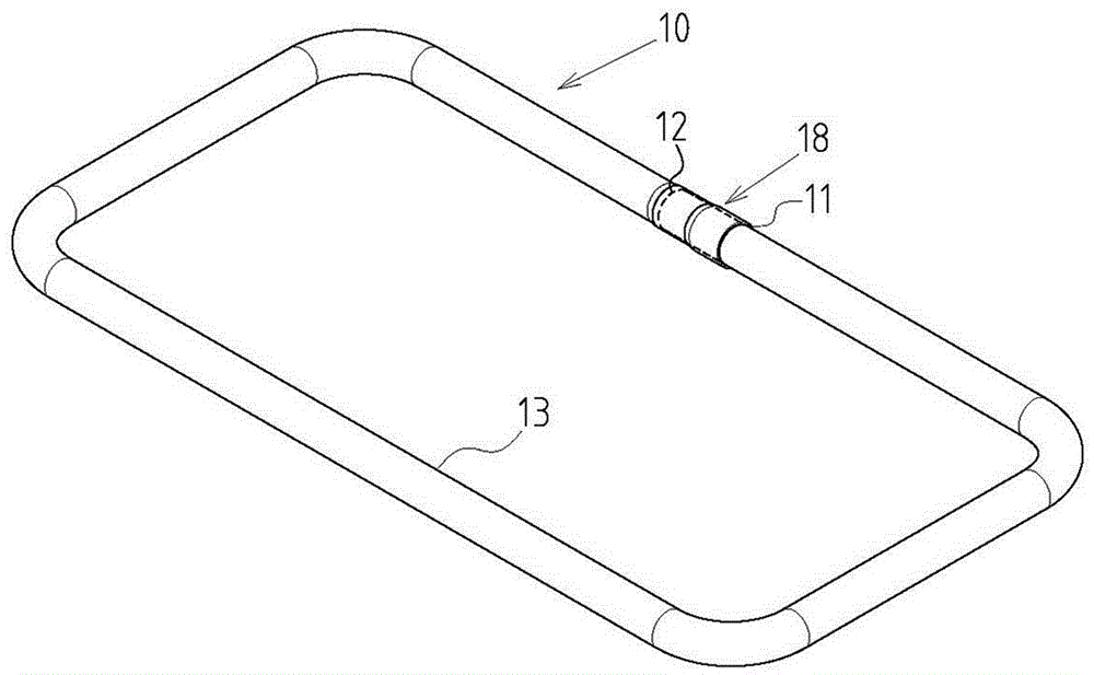
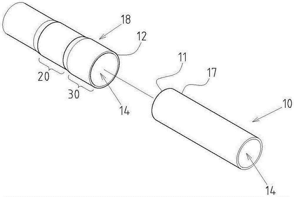
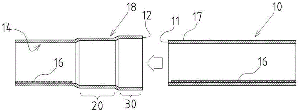
[0032] Example: see Figure 1~4 Shown are the preferred embodiments of the pipe-end butt-connected loop heat pipe and its forming method of the present invention, but these embodiments are for illustration only, and are not limited by this structure in patent application.

[0033] The tube-end butt-connected loop type heat pipe includes the following components: a hollow tube body 10, the outside of which is bent into a folded shape and includes two tube ends 11, 12 and a loop between the two tube ends 11, 12 type section 13, and a loop-type flow channel space 14 is formed inside the hollow tube body 10, which is in a vacuum-sealed state and accommodates a working fluid 15 and is provided with capillary tissue 16; part 17, set on one of the pipe ends 11 of the hollow pipe body 10; a socket part 18, set on the other pipe end 12 of the hollow pipe body 10, and the socket part 18 is used to be set on the socket Connecting portion 17 outer periphery; A tight fitting section 20 is...


PUM


Abstract

The invention provides a pipe-end butt joint type loop heat pipe and a forming method thereof. The pipe-end butt joint type loop heat pipe mainly comprises components in a structural plane as follows: a hollow pipe body, an inserting joint part, a sleeve joint part, a tight fit zone and a loose fit zone, wherein the hollow pipe body comprises two pipe ends and a loop zone, and loop channel space in the loop zone is in a vacuum closed state and accommodates a working solution; the inserting joint part is arranged at one pipe end of the hollow pipe body; the sleeve joint part is arranged at the other end of the hollow pipe body, and is assembled on the periphery of the inserting joint part in a sleeving manner; the tight fit zone is arranged in one local zone at the inserting and sleeving part of the inserting joint part and the sleeve joint part, and a tight insertion airtight state is formed between the inserting joint part and the sleeve joint part through the tight fit zone; the loose fit zone is arranged in the other local zone at the inserting and sleeving part of the inserting joint part and the sleeve joint part, and a gap is formed between the inserting joint part and the sleeve joint part through the loose fit zone. According to the pipe-end butt joint type loop heat pipe and the forming method thereof, the loop heat pipe can realize practical progress that components and manufacturing forming steps are greatly simplified, the manufacturing cost is greatly reduced and better heat dissipation efficiency is kept, and has better industrial economic benefits.

Description

technical field [0001] The invention relates to a loop-type heat pipe; in particular, it refers to an innovative technology of a pipe-end butt-connected loop-type heat pipe structure and its forming method. Background technique [0002] In view of the internal structure design of the early heat pipe, the steam flow path and the condensate flow path were arranged in the same pipe section space and were arranged in an overlapping state, so that the flow directions conflicted with each other and hindered each other, resulting in reduced heat dissipation efficiency and other problems. The industry has developed a loop-type heat pipe structure. In this heat pipe structure, the steam flow path and the condensate flow path are set in different sections in the heat pipe space, and form a loop form as a whole, so as to solve the aforementioned problems. [0003] However, the existing loop-type heat pipe structure that can be seen at present still has its shortcomings. The two ends a...

Claims


Application Information

Patent Timeline
IPC IPC(8): F28D15/04
CPCF28D15/043
Inventor 何信威黄志仁
Owner SUZHOU FORCECON ELECTRIC
Why Eureka
Try Eureka