
Stay rope displacement sensor integrated with error compensation technology, and preparation method thereof

A technology of displacement sensor and error compensation, which is applied in the field of rope displacement sensor integrated with error compensation technology and its preparation, which can solve the problems of inability to meet application requirements and limit wide application, and achieve the effect of ensuring linearity and improving accuracy

Inactive Publication Date: 2016-12-21
JIUJIANG HANTANG OPTOELECTRONICS TRANSMISSION TECH CO LTD
View PDF10 Cites 6 Cited by
  • Summary
  • Abstract
  • Description
  • Claims
  • Application Information

AI Technical Summary

Problems solved by technology

[0006] Although the rope displacement sensor has many advantages mentioned above, its measurement accuracy is its weakness at this stage. The measurement accuracy of the mainstream rope displacement sensor is 0.5mm, which is used in general occasions such as cranes, vertical slotting machines, storage location positioning, etc. It can meet the requirements, but it cannot meet the application requirements in some occasions that require higher precision, such as the precise positioning control of robot manipulators, which greatly limits its wide application.

Method used


Image

  • Stay rope displacement sensor integrated with error compensation technology, and preparation method thereof
  • Stay rope displacement sensor integrated with error compensation technology, and preparation method thereof
  • Stay rope displacement sensor integrated with error compensation technology, and preparation method thereof

Examples


Embodiment Construction

[0036] The present invention will be described in further detail below in conjunction with the embodiments and with reference to the accompanying drawings.

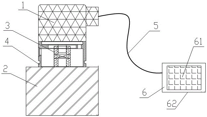
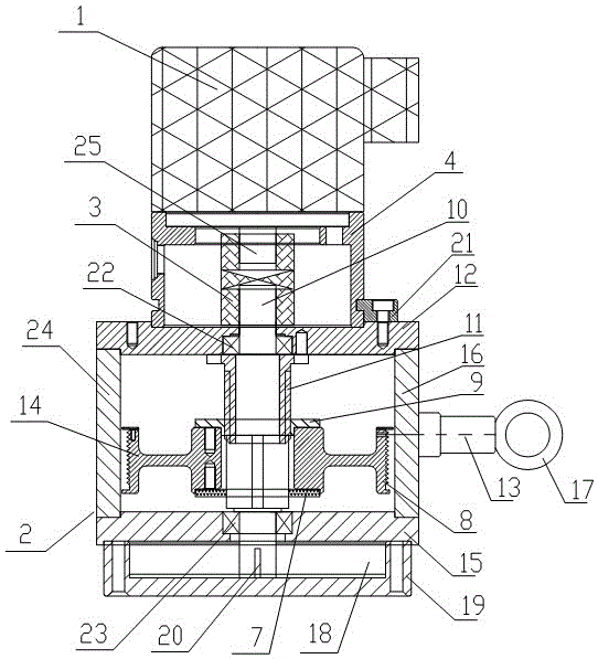
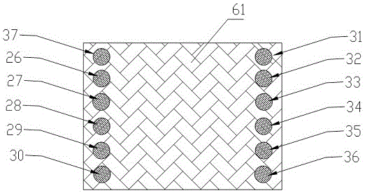
[0037] A rope displacement sensor integrating error compensation technology, including a mechanical body 2, a coupling 3, an encoder mounting base 4, a multi-turn absolute encoder 1 based on an SSI interface, a connecting cable 5, and a single-chip processing module 6 , the encoder mounting base 4 is fixed on the upper bearing seat 12 of the mechanical body 2 through the encoder mounting pressure plate 21, the multi-turn absolute encoder 1 based on the SSI interface is fixed on the top of the encoder mounting base 4, and the encoder mounting base 4 is provided with a coupling 3 in the middle, and the coupling 3 connects the main shaft 10 in the mechanical body 2 and the rotating shaft 25 in the multi-turn absolute encoder 1. The multi-turn absolute encoder based on the SSI interface 1 is connected to the processing module...


PUM


Abstract

The invention discloses a stay rope displacement sensor integrated with an error compensation technology, and a preparation method thereof. The stay rope displacement sensor comprises a mechanical body, a shaft coupling, an encoder installation seat, a multi-turn absolute encoder based on an SSI interface, a connection cable and a single-chip microcomputer processing module. When a steel wire rope on the mechanical body is drawn out, the steel wire rope drives a main shaft to rotate, the main shaft drives the multi-turn absolute encoder to rotate, the multi-turn absolute encoder outputs electric signals with angle information in a rotation process, the single-chip microcomputer processing module reads the electric signals output by the multi-turn absolute encoder, afterwards, angle data is decoded into displacement information, after original displacement information is calibrated, an error model is constructed according to a least square method, and the error model is embedded into the single-chip microcomputer processing module. The stay rope displacement sensor integrated with the single-chip microcomputer processing module has the advantage of directly outputting a displacement quantity, omits a user decoding process, at the same time, greatly improves the precision of the stay rope displacement sensor after the output displacement information is subjected to error compensation correction.

Description

technical field [0001] The invention relates to a stay rope displacement sensor, in particular to a stay rope displacement sensor integrated with error compensation technology and a preparation method thereof. Background technique [0002] The rope displacement sensor is also called the rope sensor, the rope electronic scale, and the rope encoder. The function of the rope displacement sensor is to convert the mechanical movement into an electrical signal that can be measured, recorded or transmitted. The pull rope displacement sensor is wound by a stretchable stainless steel rope on a threaded hub, which is coaxially connected with a precision rotation angle sensor, and the angle sensor can be a potentiometer or a photoelectric encoder. [0003] When the pull cord displacement sensor works, its housing is installed in a fixed position, the pull cord is tied to the moving object, and the linear motion of the pull cord is aligned with the motion axis of the moving object. Whe...

Claims


Application Information

Patent Timeline
IPC IPC(8): G01B5/04
CPCG01B5/043
Inventor 李问国
Owner JIUJIANG HANTANG OPTOELECTRONICS TRANSMISSION TECH CO LTD
Learn More