
Transformer three-layer insulated wire hot-melt crimping line high equipment and hot-melt crimping line high technology

A three-layer insulation and transformer technology, applied in the field of transformer manufacturing, can solve the problems of large differences and high defect rate, and achieve the effect of improving efficiency, saving manpower and material resources, and peeling cleanly

Active Publication Date: 2017-07-18
DONGGUAN AOHAI TECH CO LTD
View PDF3 Cites 0 Cited by
  • Summary
  • Abstract
  • Description
  • Claims
  • Application Information

AI Technical Summary

Problems solved by technology

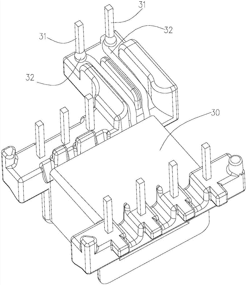
like figure 2 As shown, this method currently causes certain troubles in the transformer production process: 1. The automatic winding equipment is often limited by factors such as hardware conditions, winding wire diameter, and winding hardness. The height exceeds the transformer body; 2. When the insulated wire wound on the PIN pin is peeled by laser or other methods, the melting position and the melting loss length d of the laser peeling technology are quite different, and the defect rate is high; 3. The laser peeling equipment needs to use PIN pins Insulation is removed by facing upwards, while automatic soldering requires the PIN pins to be downwards, and an additional mechanism for turning the transformer 180 degrees must be added for automatic soldering

Method used


Image

  • Transformer three-layer insulated wire hot-melt crimping line high equipment and hot-melt crimping line high technology
  • Transformer three-layer insulated wire hot-melt crimping line high equipment and hot-melt crimping line high technology
  • Transformer three-layer insulated wire hot-melt crimping line high equipment and hot-melt crimping line high technology

Examples


Embodiment Construction

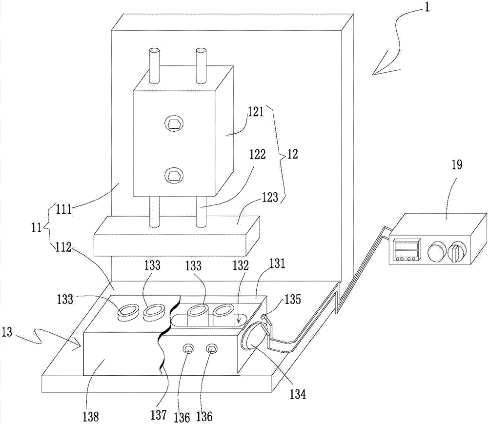
[0029] Such as Figure 3 ~ Figure 6 As shown, a transformer three-layer insulated wire hot-melt crimping equipment includes a hot-melt crimping module 1, a manipulator 2, and a PLC control module that coordinates the hot-melt crimping module 1 and the manipulator 2 to work together (not shown in the figure) show). The manipulator 2 places the transformer to be processed from the feeding place 50 on the hot-melt pressing line height module 1 to carry out the heat-melting pressing line height of the three-layer insulated wire on the transformer PIN pin 31. After the process is completed, it will The processed transformer is placed at the blanking place 60 .

[0030] The hot-melt pressure line height module 1 includes an L-shaped fixing frame 11 , the fixing frame 11 is composed of a bottom plate 112 and a vertical plate 111 , and a block-shaped hot-melt table 13 is arranged on the bottom plate 112 . Preferably, the hot-melt table 13 is in the shape of a cuboid, including the i...


PUM


Abstract

The invention discloses a transformer three-layer insulated wire hot-melt crimping high equipment, including a hot-melt crimping high module and a manipulator working in coordination under a PLC control system; the hot-melt crimping high module includes a bottom plate and a vertical plate; a block-shaped The hot-melt table is set on the bottom plate, and the hot-melt table includes the inner layer of the hot-melt table, the shell of the hot-melt table, and the heat insulation layer; there are several sets of hot-melt components in the inner layer of the hot-melt table, and the hot-melt components are connected with temperature probes. The hot-melt component and the temperature-sensing probe are jointly connected to the temperature controller by electrical communication; the corresponding hot-melt component on the vertical plate is provided with a high-pressure component that can lower the three-layer insulated wire on the PIN foot of the hot-melt component; the invention also provides a There is no need to add a PIN foot flipping mechanism for transformers with three-layer insulated wire hot-melt crimping process. After the product is processed, the PIN pin is down, which just meets the processing technology requirements of the automatic soldering machine, making the hot-melt crimping process high. Simplification, save manpower and material resources, improve equipment utilization.

Description

technical field [0001] The invention relates to the field of transformer manufacturing, in particular to a transformer three-layer insulated wire hot-melt crimping equipment and a process for hot-melting crimping. Background technique [0002] With the gradual miniaturization of electronic mobile devices, the corresponding power adapter is required to be miniaturized accordingly. The size of the transformer is an important factor in determining the size of the power adapter. In the prior art, such as figure 1 As shown, the commonly used transformer design method is that the PIN pin 31 of the output terminal (referred to as PIN pin 31) adopts three-layer insulated wire to achieve the double-layer protection required in the safety regulations, cancels the safety tape, and realizes the miniaturization design of the transformer. A three-layer insulated wire 32 of >1.5T is usually wound on the foot 31 . Such as figure 2 As shown, this method currently causes certain troubles i...

Claims


Application Information

Patent Timeline
Patent Type & Authority Patents(China)
IPC IPC(8): H01F41/076H01F41/077
Inventor 刘昊郭修根游碧锋葛中威
Owner DONGGUAN AOHAI TECH CO LTD
Learn More