
Method for machining wafer

A processing method and wafer technology, applied in the direction of stone processing equipment, fine working devices, manufacturing tools, etc., can solve the problems of device side damage and cutting edge deflection, and achieve the effect of eliminating damage and rotating stability.

Inactive Publication Date: 2016-12-21
DISCO CORP
View PDF3 Cites 8 Cited by
  • Summary
  • Abstract
  • Description
  • Claims
  • Application Information

AI Technical Summary

Problems solved by technology

[0011] However, in any of the above-mentioned processing methods, there is a problem that when the molded resin buried in the cutting groove is cut by the cutting tool, the cutting edge of the cutting tool is bent due to the resistance of the molded resin, Introduces damage to the sides of devices that make up Wafer Level Chip Scale Packages (WLCSP)

Method used


Image

  • Method for machining wafer
  • Method for machining wafer
  • Method for machining wafer

Examples


Embodiment Construction

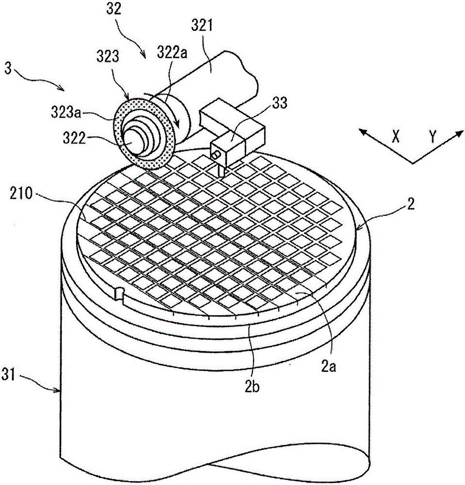
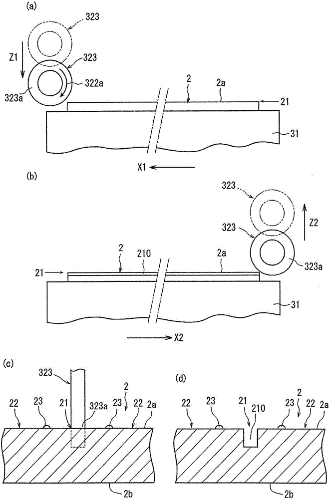
[0028] Hereinafter, preferred embodiments of the wafer processing method of the present invention will be described in detail with reference to the drawings.

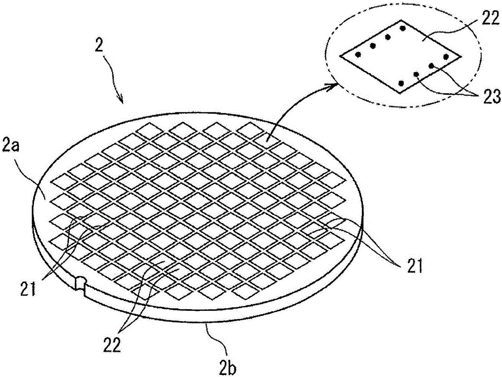
[0029] figure 1 A perspective view of a semiconductor wafer as a wafer processed according to the invention is shown in . figure 1 The shown semiconductor wafer 2 is composed of a silicon wafer with a thickness of, for example, 600 μm, and a plurality of planned dividing lines 21 are formed in a grid pattern on the front surface 2 a, and formed in a plurality of regions divided by the plurality of planned dividing lines 21 . Devices such as ICs and LSIs 22 . All the devices 22 have the same structure. A plurality of bumps 23 as protruding electrodes are respectively formed on the front surfaces of the devices 22 . Hereinafter, a wafer processing method in which the semiconductor wafer 2 is divided into individual devices 22 along the planned dividing line 21 and the respective devices are coated with resin will be de...


PUM


Abstract

Provided is a method for machining a wafer to obtain wafer-scale chip scale package (WLCSP) with good quality. The method comprises: a first cutting groove forming step, including forming a first cutting groove having a depth corresponding to the finished thickness of a device along a dividing preset line from a front side of the wafer with a cutting tool having a first thickness; a molding step, including coating the front side of the wafer subjected to the cutting groove forming step with a molded resin and embedding the molded resin in the first cutting groove; a second cutting groove forming step, including forming a second cutting groove reaching the wafer and having the depth deeper than that of the molded resin coating the front side of the wafer and that of the molded resin embedded in the molded resin with a cutting tool having a second thickness thinner than a first thickness; a protective member adhering step, including applying a protective member to the surface of the molded resin deposited on the front surface of the wafer on which the second cutting groove forming step is performed; and a back surface grinding step, including grinding the back surface of the wafer on which the protective member attaching step is carried out so that the second cutting groove is exposed to divide the wafer into individual devices.

Description

technical field [0001] The present invention relates to a processing method of a wafer, wherein a plurality of planned dividing lines are formed in a lattice shape on the front surface of the wafer and devices are formed in a plurality of regions divided by the plurality of planned dividing lines, and the wafer is formed along the planned dividing lines. The wire is divided into individual devices, and the individual devices are covered with resin. Background technique [0002] In the semiconductor device manufacturing process, a plurality of regions are divided by dividing lines arranged in a grid on the front surface of a substantially disk-shaped semiconductor wafer, and devices such as ICs and LSIs are formed in the divided regions. The semiconductor wafer formed in this way is cut along planned dividing lines to divide the regions where the devices are formed to manufacture individual devices. [0003] In recent years, packaging technology has been developed in which a...

Claims


Application Information

Patent Timeline
Patent Type & Authority Applications(China)
IPC IPC(8): H01L21/78B28D5/00
CPCH01L21/78B28D5/0005B28D5/0011
Inventor 久保敦嗣陆昕
Owner DISCO CORP
Learn More