
Assembly type electric cable trench and construction method therefor

A cable trench and assembly technology, which is applied in the direction of cable installation, cable laying equipment, ground cable installation, etc., can solve the problems that the installation process cannot be effectively simplified, the L-shaped trench body is not convenient for transportation, and the cost of transportation and storage is high. Achieve the effects of light weight, shortened construction period, and simple manufacturing process

Inactive Publication Date: 2016-12-21
河北超能投资管理有限公司 +3
View PDF16 Cites 11 Cited by
  • Summary
  • Abstract
  • Description
  • Claims
  • Application Information

AI Technical Summary

Problems solved by technology

However, this kind of integral concrete cable trench has a large volume (both width and height are more than 1.2m), and has high requirements for molds. After casting, it weighs a lot and occupies a large storage area. In particular, it is not convenient for transportation. Large-scale hoisting is required during construction. Equipment, high requirements for on-site construction, resulting in difficult construction operations, high transportation and storage costs
[0004] Aiming at the shortcomings of integrally poured reinforced concrete cable trenches, the Chinese patent application number 201410729834.6 discloses a light-weight concrete laminated plate assembled cable trench, which is composed of multiple U-shaped trenches connected by two U-shaped trenches. The semi-L-shaped ditch is formed by pouring a layer of lightweight concrete on the surface of the ditch bottom. The splicing of this structure requires on-site pouring, which will prolong the construction period, and the L-shaped ditch is not easy to transport; in order to fix the cable support, L The wall of the type ditch is relatively thick and requires small hoisting equipment, which cannot effectively simplify the installation process

Method used


Image

  • Assembly type electric cable trench and construction method therefor
  • Assembly type electric cable trench and construction method therefor
  • Assembly type electric cable trench and construction method therefor

Examples


Embodiment Construction

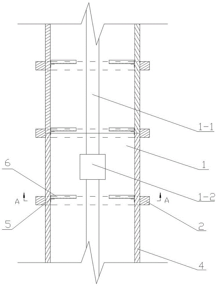
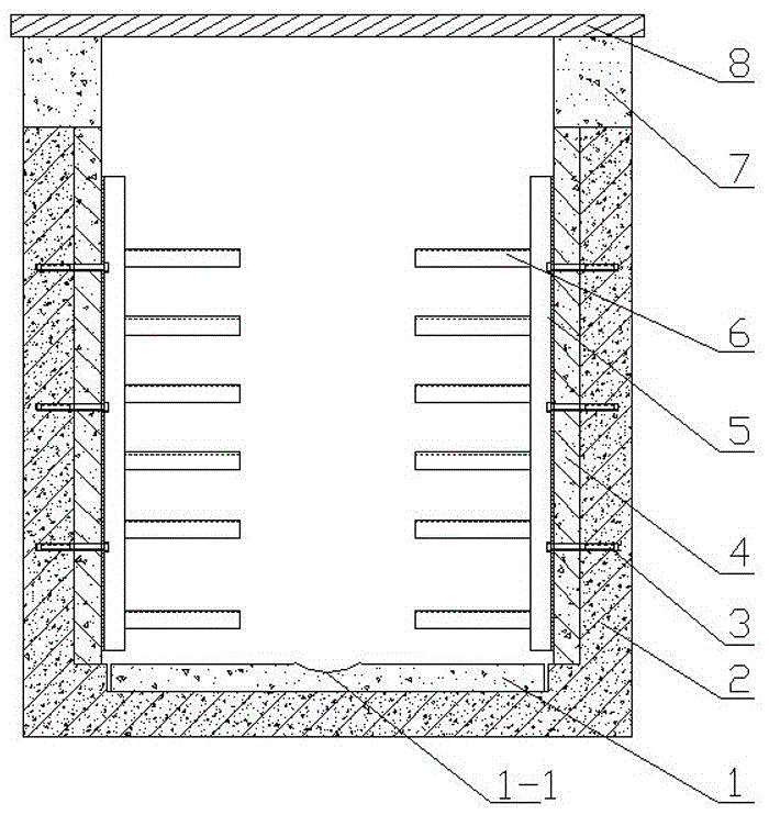
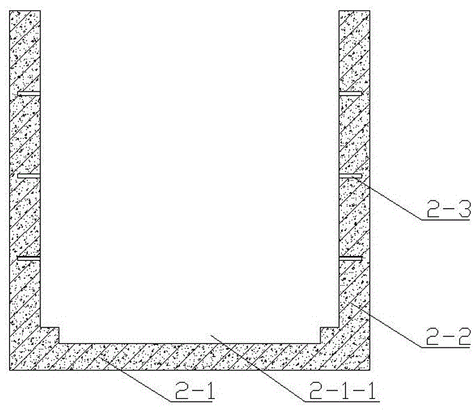
[0028] see Figure 1~Figure 3 , the cable groove of the present embodiment includes a U-shaped groove and a matching cover plate 8, and the U-shaped groove includes more than two U-shaped brackets 2 provided with assembly holes 2-3, which are connected with the U-shaped brackets in turn by means of connectors 3. The uprights on both sides of the bracket 2 are assembled with the side vertical plate 4 and the cable support 6, and the bottom plate 1 laid on the bottom of the U-shaped bracket 2. The side vertical plate 4 and the bottom plate 1 are between two or more U-shaped brackets 2. The space is assembled into a U-shaped groove with the U-shaped bracket 2 as a frame by means of the connecting piece 3 . The U-shaped brackets 2 are distributed in the length direction and interval of the cable trench, the length of the bottom plate 1 and the side vertical plate 4 is greater than the distance between the two U-shaped brackets 2, and the U-shaped brackets for the bottom plate 1 an...


PUM


Abstract

The invention discloses an assembly type electric cable trench and a manufacture method therefor. The assembly type electric cable trench comprises a U-shaped groove and a matching cover plate; the U-shaped groove comprises at least two U-shaped support racks having assembly holes, side vertical plates, electric cable support racks and base plates tiled on bottom parts of the U-shaped support racks; the side vertical plates and the electric cable support racks are respectively and orderly connected with stand columns at two sides of the U-shaped support racks in an assembled manner via use of connecting pieces; the U-shaped groove is formed between the at least two U-shaped support racks by the side vertical plates and the base plates via use of sealing gum. According to the assembly type electric cable trench, components are prefabricated or processed based on marked design; split type transport and on-site ground pit excavation are conducted; manufacture of a cushion ply layer is completed; after steel angles are welded on the cable support racks, the electric cable trench can be assembled via the connecting pieces such as screw bolts and the like. According to the assembly type electric cable trench disclosed in a technical solution of the invention, the U-shaped groove is broken up into the U-shaped support racks functioning as frames, the base plates having plate type structures and the side vertical plates; convenience of transportation can be realized, and strength of the electric cable trench is improved via the U-shaped support racks functioning as the frames.

Description

technical field [0001] The invention belongs to the technical field of electric power facilities, and in particular relates to a general-purpose assembled cable trench for a substation or a power plant and a manufacturing method thereof. Background technique [0002] At present, the design of cable trenches for substations above 220kV is made into brickwork, plain concrete, and reinforced concrete cable trenches according to the embedding depth, load size, and groundwater level to meet the cable laying requirements of substations and power plants. The cable trench often runs through the entire substation or power plant vertically and horizontally, and has high requirements on the construction progress and construction technology of the substation or power plant. Traditional brick-built cable trenches are complicated in process, require a lot of manpower and material resources, and take a long time to construct, which has a great impact on the construction progress of the pro...

Claims


Application Information

Patent Timeline
Patent Type & Authority Applications(China)
IPC IPC(8): H02G9/02H02G1/06
CPCH02G9/02H02G1/06
Inventor 布世伟陈栋徐振佳徐江勤白玉清白林杰任留通王新朝魏东亮吴春生武坤李猛韩晨鹏霍春旻王磊张瑞林周雪涛张尚华贾素华李盼义
Owner 河北超能投资管理有限公司
Learn More