Supercharge Your Innovation With Domain-Expert AI Agents!

Dynamic voltage restorer

A dynamic voltage recovery and controller technology, applied in the direction of AC network voltage adjustment, etc., can solve the problems of poor anti-shake power of inverter, poor anti-shake power of contactor, tripping, etc., to improve safety and high authority requirements , Guarantee the effect of load working voltage

Pending Publication Date: 2016-12-21
STATE GRID QINGHAI ELECTRIC POWER CO HAINAN POWER SUPPLY CO +2
View PDF3 Cites 0 Cited by
  • Summary
  • Abstract
  • Description
  • Claims
  • Application Information

AI Technical Summary

Problems solved by technology

The biggest problem with this speed control system is its poor anti-shaking ability.
[0003] 1. The speed control system is controlled by the operating console. The control circuit is designed and installed in the inverter cabinet. When the factory power is swaying, the control circuit loses power and cannot achieve the purpose of speed control.
Some DCS signal inputs require voltage-current signal conversion. This conversion module is also set in the frequency conversion cabinet. When the power grid shakes, these signals cannot be sent to the DCS.
2. The inverter itself has poor anti-shaking ability
3. The ability of 1C / 2C contactors to resist swaying electricity is poor. Many power plants have the problem that the contactor trips first when the swaying electricity occurs, but this is a superficial problem. Even if the contactor does not trip, the inverter will trip due to instantaneous power loss.

Method used


Image

  • Dynamic voltage restorer
  • Dynamic voltage restorer
  • Dynamic voltage restorer

Examples


Embodiment Construction

[0016] The present invention will be further described below in conjunction with the accompanying drawings and specific embodiments.

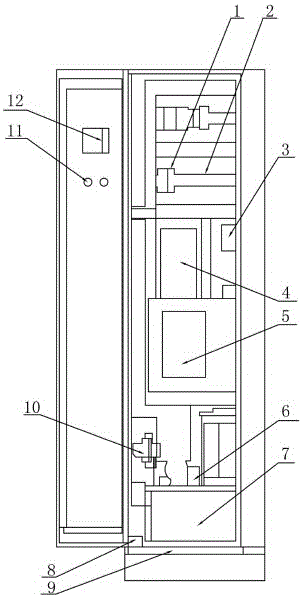
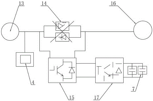
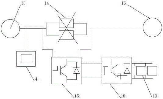
[0017] see figure 1 , figure 2 and image 3 As shown, the present invention provides a dynamic voltage restorer, including a secondary circuit control switch 1, a signal collector 2, a switching power supply 3, a controller 4, a power module 5, a filter circuit 6, a supercapacitor 7, and a ground bus Row 8, cabinet body 9, incoming line circuit 10, operation button 11, LCD touch screen 12, power system 13, anti-parallel thyristor 14, H-bridge inverter 15, load 16, DC chopper boost circuit 17, Electronic switch 18 and release resistor 19, cabinet body 9 is provided with secondary circuit control switch 1, signal collector 2, switching power supply 3, controller 4, power module 5, filter circuit 6, super capacitor 7, grounding bus bar 8 and the incoming line circuit 10, the cabinet body 9 is provided with a cabinet door, the cabinet door is p...


PUM


Abstract

The invention discloses a dynamic voltage restorer, which comprises a secondary loop control switch, a signal collector, a switching power supply, a controller, a power module, a filter loop, a super capacitor, a grounding bus bar, a cabinet body, an incoming line loop, an operation button, a liquid crystal touch screen, a power utilization system, an inverse parallel silicon controlled rectifier, an H-bridge inverter, a load, a direct-current chopped-wave boost circuit, an electronic switch and a release resistor. The secondary loop control switch, the signal collector, the switching power supply, the controller, the power module, the filter loop, the super capacitor, the grounding bus bar and the incoming line loop are arranged in the cabinet body. A cabinet door is arranged on the cabinet body. The operation button and the liquid crystal touch screen are arranged on the cabinet door. The controller and the reverse parallel silicon controlled rectifier are connected between the power utilization system and the load. The H-bridge inverter is connected between the two ends of the reverse parallel silicon controlled rectifier. The H-bridge inverter is connected with the direct-current chopped-wave boost circuit. The direct-current chopped-wave boost circuit is connected with the super capacitor. The cabinet door is provided with a fingerprint unlocking device and a wireless communication unit.

Description

technical field [0001] The invention relates to the technical field of electric equipment, in particular to a dynamic voltage restorer. Background technique [0002] At present, the frequency conversion speed regulation system of most power plants controls the speed of the frequency converter by outputting 4~20mA signal through DCS or console. The start, stop, fault and 1C / 2C power supply signals of the inverter are sent back to FSSS, and FSSS uses these signals to judge the logic of powder feeding full stop and trigger MFT action. The power distribution cabinet of the system mostly adopts 1C / 2C power supply respectively, and 3C standby self-switching switching mode. When there is MFT action, the large interlocking is used to cut off the powder frequency conversion 1C / 2C power supply. The biggest problem of this speed control system is the poor anti-shaking ability. [0003] 1. The control circuit is designed to be installed in the inverter cabinet for the system that reli...

Claims


Application Information

Patent Timeline
IPC IPC(8): H02J3/12
CPCH02J3/12
Inventor 贺岺樊海峰杨绍元田洪滨贺顺生马有俊卢耕儒张峰司庆忠
Owner STATE GRID QINGHAI ELECTRIC POWER CO HAINAN POWER SUPPLY CO
Features
  • R&D
  • Intellectual Property
  • Life Sciences
  • Materials
  • Tech Scout
  • Unparalleled Data Quality
  • Higher Quality Content
  • 60% Fewer Hallucinations
Learn More