Crushing and nail-removing machine for building plastic template

A technology for plastic formwork and construction, applied in plastic recycling, mechanical material recycling, recycling technology, etc., can solve the problems of low efficiency, high power, and high energy consumption, and achieve high efficiency, high speed, and small volume.

Inactive Publication Date: 2017-01-04
田涛
View PDF2 Cites 2 Cited by
  • Summary
  • Abstract
  • Description
  • Claims
  • Application Information

AI Technical Summary

Problems solved by technology

[0003] The existing separation and crushing equipment for plastic templates for construction has low efficiency and large dust, which is difficult to meet the needs of large-scale crushing. Most pulverizers install the moving knife blade on the cutter head and rotate with the cutter head, but the moving knife blade needs to be used. Cooperate with the cutting action of the fixed knife, and the impact and collision of the blade on the broken object to realize the crushing function
There are also some pulverizers that use the feeding mechanism to feed materials, and use multiple sets of electric saws to cut the boards. The saw blades are circularly cut and fed, which affects the efficiency of milling, and the power is high and the energy consumption is high.
In addition, many waste boards inevitably contain connectors such as iron nails, which are easy to damage the milling machine. The existing pulverizers and cutting machines cannot saw wood-plastic boards and profiles with nails.
At present, before cutting and crushing, the nails are manually pulled out, which is inefficient and labor-intensive
Iron nails are not easy to be screened and removed during milling and crushing, and will be mixed into wood flour products, affecting the subsequent milling process
[0004] The Chinese patent "Wood-plastic formwork powder making machine" (CN203916823U) discloses a powder making machine for building formwork. This patent drags the building plastic formwork into the pressure roller through the upper pressure roller and the lower pressure roller, and sends it to the crushing roller. The plastic formwork is crushed by the moving knife (column rod) on the crushing roller. This patent can crush the plastic formwork better, but the cost is high because the front end is equipped with a pressure roller. In addition, through the moving knife (cylindrical rod) Broken plastic formwork, loud noise
[0005] The Chinese patent "wood-plastic composite profile cutting machine" (CN203765681U) discloses a cutting machine for wood-plastic composite material profiles. This patent uses the upper and lower pressure rollers to drag the building plastic formwork into the pressure rollers. The plastic template is crushed by the saw blade. This patent uses a cutting saw, which is noisy

Method used


Image

  • Crushing and nail-removing machine for building plastic template
  • Crushing and nail-removing machine for building plastic template
  • Crushing and nail-removing machine for building plastic template

Examples


Embodiment Construction

[0027] The present invention is described in further detail below in conjunction with accompanying drawing:

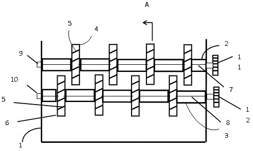
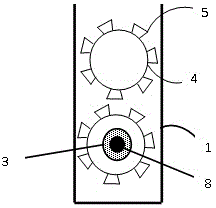
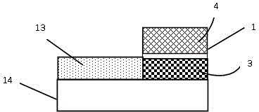
[0028] See attached image 3 , a construction plastic formwork pulverizer, comprising a support 1, a feeding table 12, an upper cutter roller, and a lower cutter roller

[0029] See attached figure 1 , figure 2 and image 3 , a construction plastic formwork pulverizer, comprising a support 1, a feed table 12, an upper cutter roller, and a lower cutter roller, the upper cutter roller and the lower cutter roller are arranged up and down on the support; the upper cutter roller includes an upper cutter roller Frame 2, upper main shaft 7, upper bearing seat 9 and upper driving wheel 12, the upper knife roller frame 2 is installed on the upper main shaft 7, and two upper bearing seats 9 are respectively arranged at both ends of the upper knife roller frame 2 And the upper knife roller frame 2 is fixedly arranged on the support 1, and the upper driving wheel 11 is arrang...


PUM


Abstract

The invention provides a crushing and nail-removing machine for a building plastic template. The machine comprises a support, a feeding bench, an upper knife roller, and a lower knife roller. A plurality of upper cutter heads and lower cutter heads are arranged on upper and lower knife roller supports at an interval, respectively. Each lower cutter head is provided with a plurality of cutting tools, and the upper cutter heads arranged on the upper knife roller support and the lower cutter heads arranged on the lower knife roller support are in spaced staggered arrangement. An axis of the upper knife roller support is higher than the feeding bench, and an axis of the lower knife roller support is lower than the feeding bench. Ends of the upper and lower knife roller supports are located on the support through bearing pedestals. Since the rotary speeds of the upper and lower knife roller supports are different, a building plastic template is dragged in the place between the upper and lower knife roller supports. When the building plastic template enter the place between the upper and lower knife roller supports, the knife rollers drive the cutter heads to rotate, and the cutting tools arranged on the cutter heads crush the template at different time. Through the spaced staggered arrangement of the upper cutter heads of the upper knife roller support and the lower cutter heads of the lower knife roller support, nails in the template can be separated.

Description

technical field [0001] The invention relates to a building plastic formwork crushing and nail removal machine, which belongs to the technical field of building formwork crushing. Background technique [0002] With the rapid development of the construction industry, the status of formwork engineering has become increasingly prominent. Formwork technology directly affects the quality, cost and efficiency of engineering construction. At the same time, concepts such as green, low-carbon, and sustainable have gradually become hot spots in various engineering applications. In recent years, with the continuous development of the plastic industry, architectural plastic formwork has emerged as the times require, which combines the advantages of wood and plastic, such as weather resistance, reliability, environmental protection, convenience, and more importantly, recyclable reuse. [0003] The existing separation and crushing equipment for plastic templates for construction has low ef...

Claims


Application Information

Patent Timeline
Patent Type & Authority Applications(China)
IPC IPC(8): B02C18/14B02C18/18B29B17/02B29B17/04
CPCY02W30/52Y02W30/62
Inventor 田涛陈兴华
Owner 田涛
Why Eureka
Try Eureka