Automatic forming machine of thin-walled short U bent pipe with welding ring

An automatic forming machine and pipe bending technology, which is applied in the direction of feeding device, positioning device, storage device, etc., can solve the problems of difficult multi-point clamping, limited clamping and positioning area, waste of pipe material, etc.

Active Publication Date: 2017-01-04
TONGLU QIANDING TECH
View PDF10 Cites 19 Cited by
  • Summary
  • Abstract
  • Description
  • Claims
  • Application Information

AI Technical Summary

Problems solved by technology

[0005] ①Using pipe bending first + pipe cutting later: a continuous production line is formed by combining the pipe bending machine, pipe cutting machine and pipe material transmission line. In the process of pipe bending and then pipe cutting, it is necessary to cut and saw the short U bend pipe, and the pipe material A large amount of metal shavings are likely to be produced during the sawing process, so the subsequent process needs to increase the cleaning and deletion process. At the same time, the pipe material needs to be cut off the folded and deformed part of the end of the bent pipe during the sawing process. According to statistics, the cut waste accounts for 20% of the raw materials. %, so this scheme will also cause a large waste of pipe material;
[0006] ②Adopt pipe cutting first + pipe bending later: Zhangjiagang Jiangsu University of Science and Technology Industrial Technology Research Institute and Jiangsu University of Science and Technology jointly disclosed a bending forming production line (Chinese Patent Publication No.: CN104826925A), which includes an unwinding mechanism and a feeding straightening device , cutting mechanism, bending forming equipment and feeding mechanism, wherein the bending forming equipment clamps the pipe material through the central clamping device, and the left and right double heads are individually bent. Although the left and right bending forming devices are equipped with clamping devices, the pipe can be It plays a role in positioning during the bending process, but for the forming of thin-walled short U elbows, except for the middle part of the straight pipe section at both ends, it needs to be bent and deformed, which also means that the clamping and positioning area is limited during the bending process. It is not easy to clamp at multiple points. If this scheme is used to process thin-walled short U-bend pipes, ...

Method used


Image

  • Automatic forming machine of thin-walled short U bent pipe with welding ring
  • Automatic forming machine of thin-walled short U bent pipe with welding ring
  • Automatic forming machine of thin-walled short U bent pipe with welding ring

Examples


Embodiment Construction

[0085] The present invention will be further described below, but the present invention is not limited to the following embodiments.

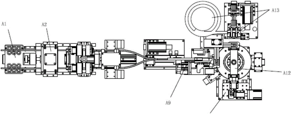
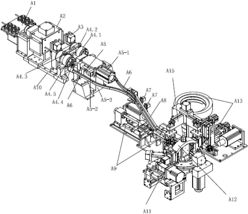
[0086] Such as Figure 1 to Figure 3 As shown, an automatic forming machine for thin-walled short U-bend pipes with welding rings includes the following parts: a feeding assembly A1, with at least one clamping mechanism A2 and a No. 1 driving mechanism (motor and screw nut pair), The pipe A14 is clamped by the clamping mechanism, and the material is fed forward under the drive of the No. 1 drive mechanism; the cutting assembly A4 has at least one cutter mechanism and the No. 2 drive mechanism (motor), and the tool is driven by the No. 2 drive mechanism. Cut the pipe into fixed-length pipe A14.1; an elbow assembly A9, with at least one fixed part, one semicircular die, one movable part and the third drive mechanism A9.7 (motor), one end of the fixed-length pipe is clamped At the fixed part, the other end is movably fitted to the movable part after ...


PUM


Abstract

The invention discloses an automatic forming machine of a thin-walled short U bent pipe with a welding ring, relates to the technical field of automation equipment, and can continuously accomplish the forming of the thin-walled short U bent pipe and socket welding ring operation, so as to prevent a pipe wall from folds. The automatic forming machine comprises a feeding assembly, a pipe cutting assembly, a pipe bending assembly, a circumference position rotating assembly and a socket welding ring assembly, wherein the feeding assembly at least comprises a clamping mechanism and a No.1 driving mechanism; the No.1 driving mechanism drives the clamping mechanism to perform forward feeding; the pipe cutting assembly at least comprises a cutting tool mechanism and a No.2 driving mechanism; the No.2 driving mechanism drives a cutting tool to act; the pipe bending assembly at least comprises a fixed part, a semicircle die, a movable part and a No.3 driving mechanism; one end of a fixed length pipe is clamped at the fixed part; the other end of the fixed length pipe gets over the semicircle die and then is movably matched with the movable part; the circumference position rotating assembly at least comprises a rotating frame, a pipe clamping mechanism, a No.4 driving mechanism and a discharging cylinder; the socket welding ring assembly at least comprises a welding ring feeding unit, a welding ring guide unit and a socket welding ring unit; the socket welding ring unit pushes the welding ring to a straight pipe section of the thin-walled short U bent pipe.

Description

Technical field [0001] The invention relates to the technical field of automation equipment, in particular to an automatic forming machine for thin-walled short U-bend pipes with welding rings. Background technique [0002] With the continuous progress of science and technology and the rapid development of industrial production, the demand for bent pipes in the industry has gradually increased. The quality of the bent pipes will directly affect the structural rationality, safety and reliability of these products. Sex. The thin-walled short U elbow with welding ring is the main component of the heat exchanger, and it is widely used in heat exchangers, air conditioners, refrigerators and other equipment. [0003] The existing thin-walled short U-bend pipes with welded rings on the market basically adopt manual or semi-automatic operation, whether it is the bending pipe forming process or the welding ring process, which has high labor intensity, low efficiency and poor forming accura...

Claims


Application Information

Patent Timeline
IPC IPC(8): B21D43/00B21D3/02B21D9/05B23P23/04
CPCB21D3/02B21D9/05B21D43/003B21D43/006B23P23/04
Inventor 潘炎忠
Owner TONGLU QIANDING TECH
Why Eureka
Try Eureka