
Intermediate-frequency welding control system

A technology of control system and intermediate frequency, which is applied in the direction of welding monitoring device, welding power supply, welding equipment, etc., to achieve the effect of improving efficiency, saving energy and increasing the use function

Inactive Publication Date: 2017-01-04
合肥国声电子通信有限责任公司
View PDF6 Cites 1 Cited by
  • Summary
  • Abstract
  • Description
  • Claims
  • Application Information

AI Technical Summary

Problems solved by technology

[0004] However, in the actual welding production process, there are many factors that affect the welding quality, such as network voltage fluctuations, shunts, electrode wear, and assembly quality, etc.

Method used


Image

  • Intermediate-frequency welding control system
  • Intermediate-frequency welding control system
  • Intermediate-frequency welding control system

Examples


Embodiment Construction

[0029] Combine below Figure 1 to Figure 6 , the present invention is further described:

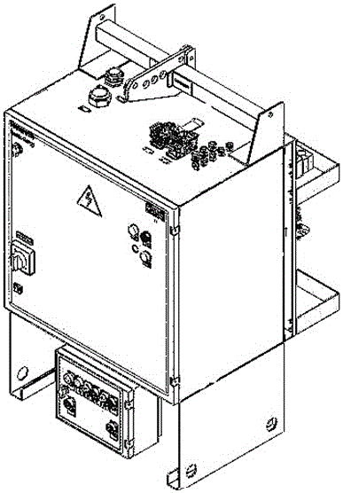
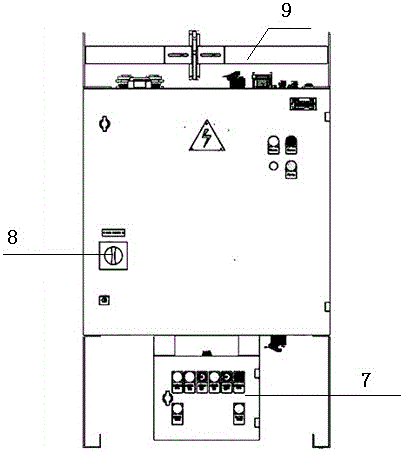
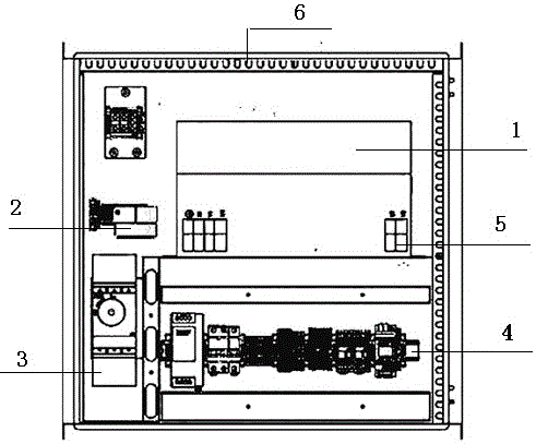
[0030] Such as figure 1 As shown, an intermediate frequency welding control system, the control cabinet is equipped with a welding controller 1, a 1000HZ induction coil 2, a main power circuit breaker 3 and a 1000HZ monitor 4, and the welding controller 1 is equipped with a main power supply for the welding torch welding transformer. Welding controller main power secondary end 5, grounding copper plate 6 is provided on the top of the control cabinet; main power circuit breaker rotary handle 8 is provided on the front door of the control cabinet, and the main power circuit breaker rotary handle 8 controls the main power disconnection 3; on the upper end of the back of the control cabinet, there is a welding torch water and gas pipe and a signal cable pipe clamp 16, and on the lower end of the back of the control cabinet, there is a protective fence 17, and on the lower end of the back of...


PUM


Abstract

The invention relates to an intermediate-frequency welding control system. According to the intermediate-frequency welding control system, heat transferred by cooling water each time is monitored, thereby reckoning whether next heat exchange meets the demand or not; and once the next heat exchange does not meet the demand, the heat transfer amount is increased by sequentially adopting a method for improving the flow rate and a method for lowering temperature with cooling water, thereby saving energy and ensuring the welding quality of an electrode holder.

Description

technical field [0001] The invention relates to an intermediate frequency welding control system. Background technique [0002] With the development of science and technology and the improvement of manufacturing technology, welding technology has been used more and more in mechanical structures. Compared with other processing techniques, welding technology has outstanding advantages, such as relatively simple equipment structure, good on-site performance, and adaptability to various working conditions. The prominence of these advantages also puts forward higher requirements for welding equipment. As an important part of the welding machine, the resistance welding machine plays an important role in fields such as automobiles, aerospace, and home appliances due to its unique technological characteristics. [0003] At present, the development of the entire automobile industry is moving towards saving resources and reducing environmental pollution. Reducing the weight of auto...

Claims


Application Information

Patent Timeline
Patent Type & Authority Applications(China)
IPC IPC(8): B23K11/25B23K11/36
CPCB23K11/25B23K11/36
Inventor 姜继贤李琪
Owner 合肥国声电子通信有限责任公司
Learn More