Integrated welding device for microwave component

A microwave component and welding device technology, applied in auxiliary devices, welding equipment, auxiliary welding equipment, etc., can solve the problems of poor welding quality consistency, low welding efficiency, affecting welding quality, etc., and achieve good welding quality consistency and welding positioning. High precision, convenient and quick installation

Active Publication Date: 2017-01-04
SHANGHAI SPACEFLIGHT INST OF TT&C & TELECOMM
View PDF8 Cites 13 Cited by
  • Summary
  • Abstract
  • Description
  • Claims
  • Application Information

AI Technical Summary

Problems solved by technology

[0004] 1. Solder paste needs to be applied before welding the glass beads and connectors. During the welding process, the solder is manually filled while heating. The welding efficiency is low. The amount of solder manually filled with solder cannot be controlled, and the welding quality is poor.
[0005] 2. It takes a long time to heat the glass beads and connectors one by one. When welding the glass beads, it is easy to cause remelting of the glass beads, connectors or substrates next to them. The welding process is prone to voids, poor penetration rate, and poor welding air tightness. The glass beads and connectors are not continuously pressurized, which may easily cause the glass beads or connectors to be skewed, and the welding positioning accuracy cannot be guaranteed
[0006] 3. When welding the side connector, the side is pressurized by rotation, such as patent CN 201988820 U, a welding tool for radio frequency connectors, an

Method used


Image

  • Integrated welding device for microwave component
  • Integrated welding device for microwave component
  • Integrated welding device for microwave component

Examples


Embodiment Construction

[0041] In order to make the object, technical solution and advantages of the present invention clearer, various embodiments of the present invention will be described in detail below in conjunction with the accompanying drawings.

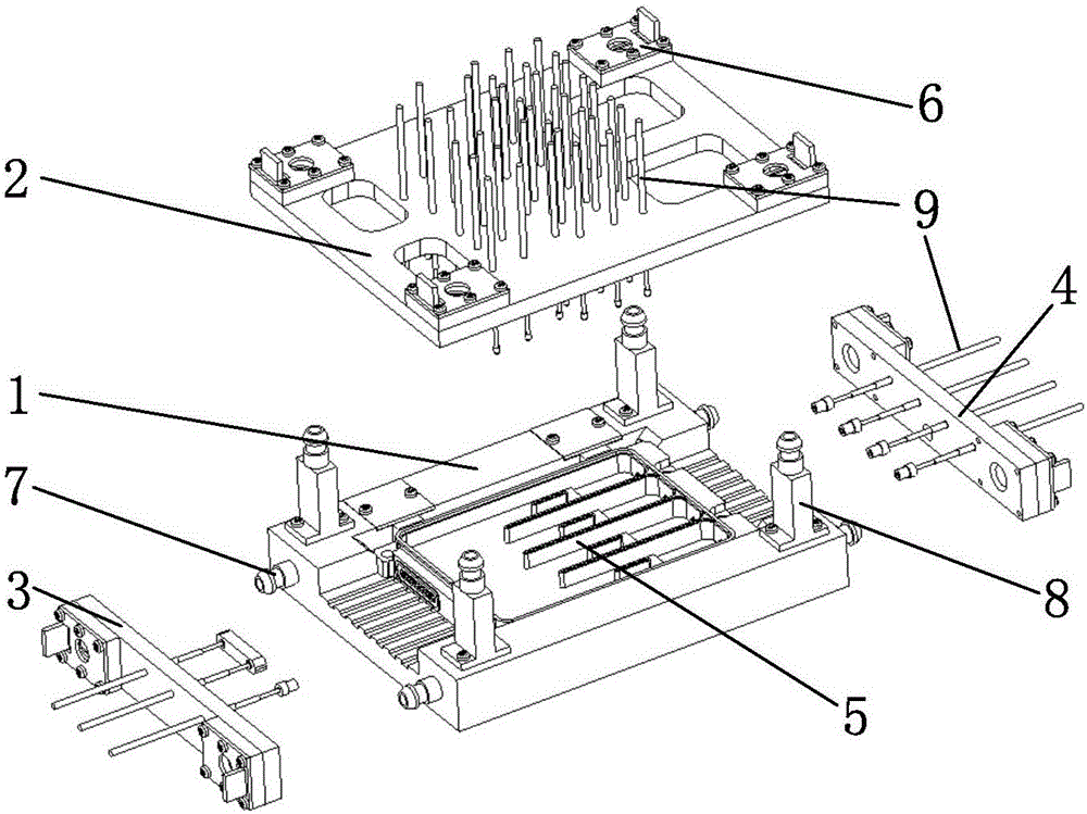
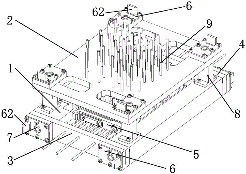
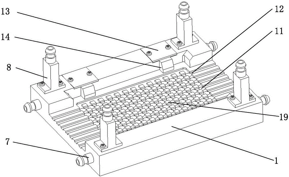
[0042] Please refer to the following Figure 1 to Figure 12 , an integrated welding device for microwave components 5, used for welding microwave components 5 including a box body 51, a microwave substrate 57, a glass bead 52 and a connector 54, which includes a base 1, an upper pressing module 2, a left Press die group 3 and right press die group 4; Wherein,

[0043]The left pressing module 3 includes a left pressing block 31, a self-locking buckle 6 and a pogo pin 9, the right pressing module 4 includes a right pressing block 41, a self-locking buckle 6 and a pogo pin 9, and the upper pressing module 2 includes an upper pressing Block 23, self-locking buckle 6 and pogo pin 9, left pressing block 31, right pressing block 41 and upper pressing bloc...


PUM


Abstract

The invention discloses an integrated welding device for a microwave component, which is used for welding the microwave component composed of a box body, a microwave substrate, a glass bead and a connector. The integrated welding device comprises a base, an upper pressing module, a left pressing module and a right pressing module. The left pressing module comprises a left pressing block, self-locking buckles and a spring needle; the right pressing module comprises a right pressing block, self-locking buckles and a spring needle; the upper pressing module comprises an upper pressing block, self-locking buckles and a spring needle. The self-locking buckles are mounted on the left pressing block, the right pressing block and the upper pressing block. Positioning pins are mounted on the base. The self-locking buckles are buckled with the positioning pins, so that the left pressing block, the right pressing block and the upper pressing block are respectively fixedly connected with the base. A spring needle hole is formed in each of the left pressing block, the right pressing block and the upper pressing block, and each of the spring needles is mounted on the corresponding spring needle hole, so that the left pressing block, the right pressing block and the upper pressing block compress the microwave component through the spring needles. The integrated welding device disclosed by the invention has the advantages of being high in welding efficiency, good in welding quality consistency, high in welding and positioning precision, free from product damage in the assembly process, good in reliability, simple to operate and the like.

Description

technical field [0001] The invention relates to an integrated welding device for electronic products, in particular to an integrated welding device for aerospace microwave components. Background technique [0002] The microwave component is the basis of the active phased array radar antenna and the core component of the active phased array radar. The consistency of the welding quality of the microwave component directly affects the overall machine index of the radar. An active phased array radar requires dozens or hundreds of components, or tens of thousands of microwave components. The welding of box body, microwave substrate, glass beads and connectors of microwave components is the basis of microwave component welding, and its welding quality directly affects the performance of microwave components. [0003] At present, the welding of microwave component boxes, microwave substrates, glass beads, and connectors is mainly carried out in the following steps. First, the micr...

Claims


Application Information

Patent Timeline
IPC IPC(8): B23K37/00B23K37/04
CPCB23K37/00B23K37/0443B23K2101/36
Inventor 赵涌曹向荣吴伟伟杨宇恺王立春
Owner SHANGHAI SPACEFLIGHT INST OF TT&C & TELECOMM
Why Eureka
Try Eureka