Electric insulated clamp

An insulating clamp, electric power technology, applied in the direction of pliers, manufacturing tools, hand-held tools, etc., can solve the problems of insufficient occlusal force, poor insulation performance, etc., to increase friction, ensure insulation coefficient, and increase friction coefficient. Effect

Inactive Publication Date: 2017-01-04
NANYANG POWER SUPPLY COMPANY OF STATE GRID HENAN ELECTRIC POWER
View PDF9 Cites 2 Cited by
  • Summary
  • Abstract
  • Description
  • Claims
  • Application Information

AI Technical Summary

Problems solved by technology

[0008] In view of this, the purpose of the present invention is to address the deficiencies of the prior art, to provide a kind of electric i...

Method used


Image

  • Electric insulated clamp
  • Electric insulated clamp
  • Electric insulated clamp

Examples


Embodiment 1

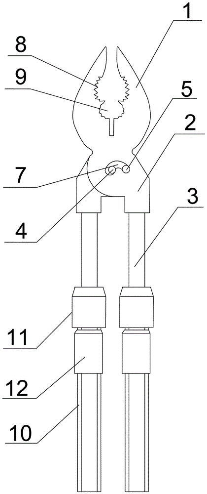
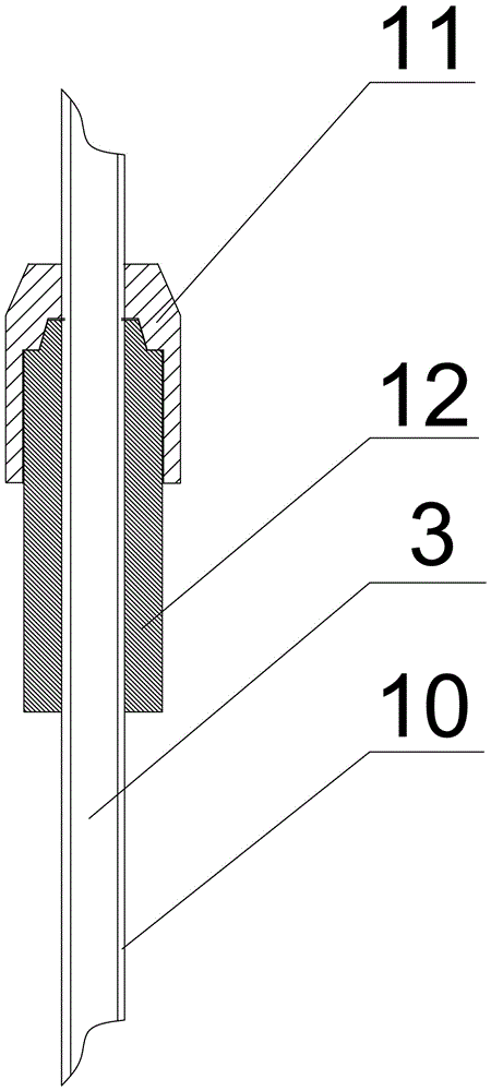
[0035] Such as Figure 1-3 As shown, an electrically insulated clamp includes two clamp bodies and a connecting mechanism. The clamp body includes a clamp mouth 1, a clamp jaw 2 and a clamp handle 3 that are sequentially connected. The jaw 1 and the jaw 2 are an integral structure. The handle 3 is fixedly connected with the jaw 2;

[0036] The two pliers bodies are connected together by a connecting mechanism arranged in the center of the pliers body. The connecting mechanism includes a main connecting hole 4, a secondary connecting hole 5 and a connecting shaft 6, and a sliding groove 7 is provided between the main connecting hole 4 and the secondary connecting hole 5. , The inner diameter of the main connecting hole 4, the inner diameter of the auxiliary connecting hole 5, and the groove width of the sliding groove 7 are respectively adapted to the diameter of the connecting shaft 6. In this embodiment, the connecting shaft 6 is located in the main connecting hole 4; the top of...

Embodiment 2

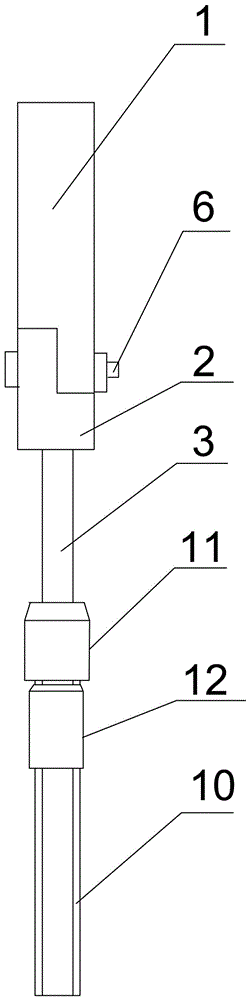
[0045] Such as Figure 4 As shown, an electrically insulated clamp includes two clamp bodies and a connecting mechanism. The clamp body includes a clamp mouth 1, a clamp jaw 2 and a clamp handle 3 that are sequentially connected. The jaw 1 and the jaw 2 are an integral structure. The handle 3 is fixedly connected with the jaw 2;

[0046] The two pliers bodies are connected together by a connecting mechanism arranged in the center of the pliers body. The connecting mechanism includes a main connecting hole 4, a secondary connecting hole 5 and a connecting shaft 6, and a sliding groove 7 is provided between the main connecting hole 4 and the secondary connecting hole 5. , The inner diameter of the main connecting hole 4, the inner diameter of the auxiliary connecting hole 5, and the groove width of the sliding groove 7 are respectively adapted to the diameter of the connecting shaft 6. In this embodiment, the connecting shaft 6 is located in the auxiliary connecting hole 5; the top ...

Embodiment 3

[0055] Such as Figure 5 As shown, an electrically insulated clamp includes two clamp bodies and a connecting mechanism. The clamp body includes a clamp mouth 1, a clamp jaw 2 and a clamp handle 3 that are sequentially connected. The jaw 1 and the jaw 2 are an integral structure. The handle 3 is fixedly connected with the jaw 2;

[0056] The two pliers bodies are connected together by a connecting mechanism arranged in the center of the pliers body. The connecting mechanism includes a main connecting hole 4, a secondary connecting hole 5 and a connecting shaft 6, and a sliding groove 7 is provided between the main connecting hole 4 and the secondary connecting hole 5. , The inner diameter of the main connecting hole 4, the inner diameter of the auxiliary connecting hole 5 and the groove width of the sliding groove 7 are respectively adapted to the diameter of the connecting shaft 6; the top of the jaw 1 is provided with a first jaw 8, which is located near the end of the jaw 2 Th...


PUM


Abstract

The invention discloses an electric insulated clamp. The electric insulated clamp comprises two clamp bodies and a connecting mechanism, wherein each clamp body comprises a jaw, a cheek and a handle which are connected in sequence; the jaw and the cheek form an integral structure; the handle is fixedly connected with the cheek; the two clamp bodies are connected into a whole body through the connecting mechanism arranged in the centers of the clamp bodies; the connecting mechanism comprises a main connecting hole, an auxiliary connecting hole and a connecting shaft; a sliding chute is formed between the main connecting hole and the auxiliary connecting hole. The electric insulated clamp solves the problem that the jaw of the existing insulated clamp is insufficient in bite force and poor in insulating property.

Description

Technical field [0001] The invention relates to the field of electric power maintenance equipment, in particular to an electric insulation clamp. Background technique [0002] In the process of live working, it is necessary to use various insulating tools to work far away from live objects. Insulating clamps are one of the commonly used insulating tools. With the help of insulating clamps, operators can realize operations such as clamping and fixing of live objects beyond a safe distance. [0003] The Chinese patent with the authorized announcement number CN 204209573 U discloses an insulated clamp including: two clamp bodies, each of the clamp bodies includes a jaw section, a pliers handle section, and a pliers located between the jaw section and the The pivotal part between the pliers handle segments, the two pivotal parts of the two pliers bodies are pivotally connected by a connecting piece, and the two jaw sections of the two pliers bodies have clamping The clamping state of...

Claims


Application Information

Patent Timeline
IPC IPC(8): B25B7/10B25B7/02B25G1/12C08L27/06C08L91/00C08L9/02C08K13/02C08K5/11C08K5/12C08K5/372C08K3/34
CPCB25B7/02B25B7/10B25G1/12C08K2201/014C08L27/06C08L2205/03C08L91/00C08L9/02C08K13/02C08K5/11C08K5/12C08K5/372C08K3/346
Inventor 王坤李成彦李宴都王欢庄严马洪举张汶卓马建波张继凯全晓王海涛赵炎辉陈鹏尹应军王添张义强胡新泉王峰杨子垲段君丽
Owner NANYANG POWER SUPPLY COMPANY OF STATE GRID HENAN ELECTRIC POWER
Why Eureka
Try Eureka