Power Insulation Clamp

A technology of insulating clamps and electric power, applied in pliers, manufacturing tools, hand-held tools, etc., can solve problems such as insufficient bite force and poor insulation performance, and achieve the goal of increasing friction, ensuring insulation coefficient, and ensuring construction safety Effect

Inactive Publication Date: 2018-04-20
NANYANG POWER SUPPLY COMPANY OF STATE GRID HENAN ELECTRIC POWER
View PDF9 Cites 0 Cited by
  • Summary
  • Abstract
  • Description
  • Claims
  • Application Information

AI Technical Summary

Problems solved by technology

[0008] In view of this, the purpose of the present invention is to address the deficiencies of the prior art, to provide a kind of electric insulation clamp, which solves the problems of insufficient bite force and poor insulation performance of the jaws of the existing insulation clamp.

Method used


Image

  • Power Insulation Clamp
  • Power Insulation Clamp
  • Power Insulation Clamp

Examples


Embodiment 1

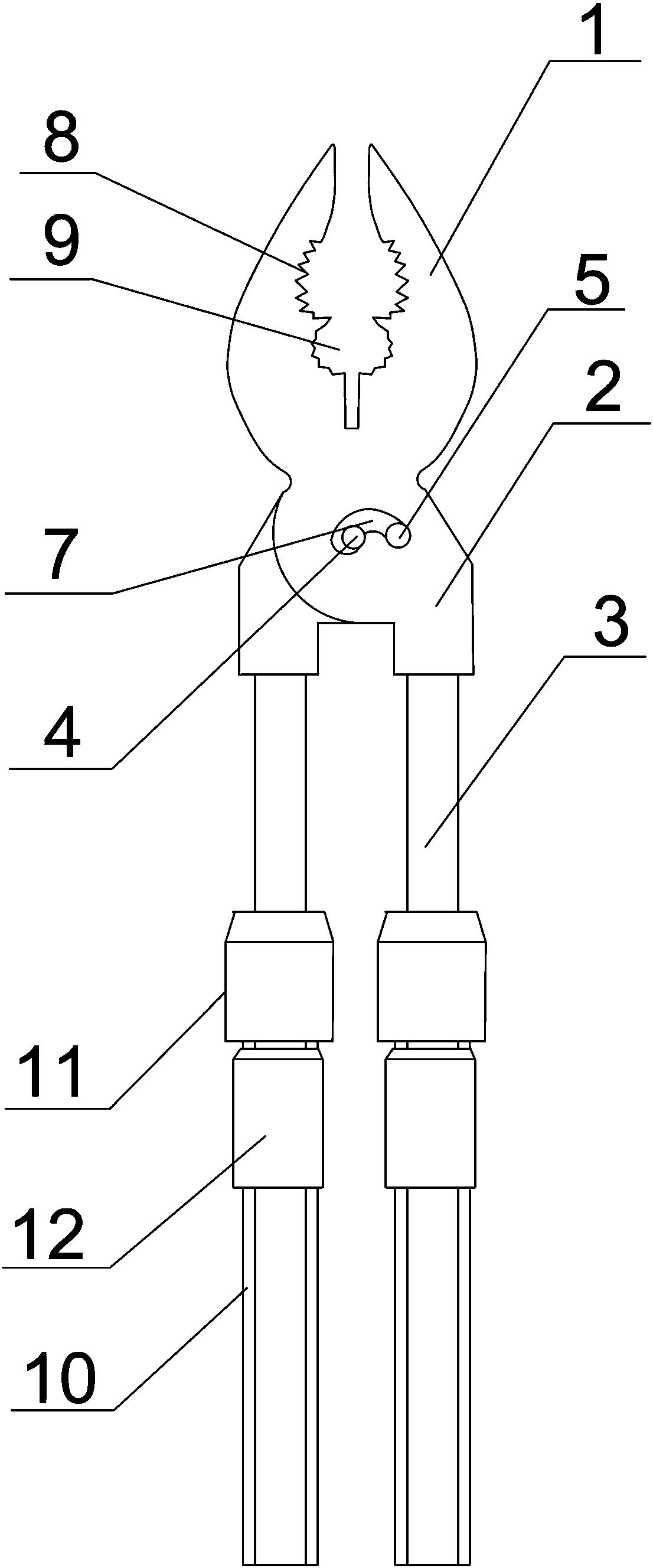
[0035] like Figure 1-3 As shown in the figure, an electrical insulating clamp includes two clamp bodies and a connecting mechanism. The clamp body includes a clamp mouth 1, a clamp jaw 2 and a clamp handle 3 connected in turn. The clamp jaw 1 and the clamp jaw 2 are integrally formed. The handle 3 is fixedly connected with the jaw 2;

[0036] The two pliers are connected together by a connecting mechanism arranged in the center of the pliers. The connecting mechanism includes a main connecting hole 4, an auxiliary connecting hole 5 and a connecting shaft 6, and a chute 7 is arranged between the main connecting hole 4 and the auxiliary connecting hole 5. , wherein the inner diameter of the main connection hole 4, the inner diameter of the auxiliary connection hole 5 and the slot width of the chute 7 are respectively adapted to the diameter of the connection shaft 6. In this embodiment, the connection shaft 6 is located in the main connection hole 4; A first jaw 8 is provided,...

Embodiment 2

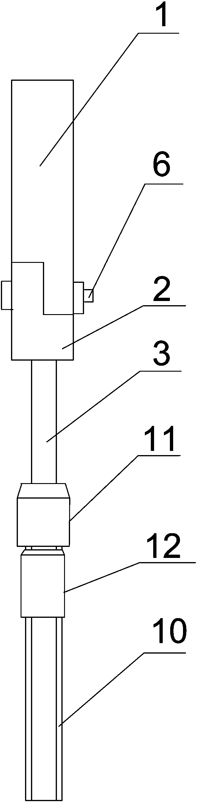
[0045] like Figure 4 As shown, a kind of electric insulation clamp includes two clamp bodies and a connecting mechanism. The clamp body includes a jaw 1, a jaw 2 and a handle 3 connected in sequence. The mouth 1 and jaw 2 are integrally formed. The handle 3 is fixedly connected with the pliers jaw 2;

[0046] The two pliers are connected together by a connecting mechanism arranged in the center of the pliers. The connecting mechanism includes a main connecting hole 4, a secondary connecting hole 5 and a connecting shaft 6, and a slide groove 7 is arranged between the main connecting hole 4 and the secondary connecting hole 5. , wherein the inner diameter of the main connecting hole 4, the inner diameter of the auxiliary connecting hole 5 and the groove width of the chute 7 are adapted to the diameter of the connecting shaft 6 respectively, and the connecting shaft 6 is located in the auxiliary connecting hole 5 in this embodiment; A first jaw 8 is provided, a second jaw 9 is...

Embodiment 3

[0055] like Figure 5 As shown, a kind of electric insulation clamp includes two clamp bodies and a connecting mechanism. The clamp body includes a jaw 1, a jaw 2 and a handle 3 connected in sequence. The mouth 1 and jaw 2 are integrally formed. The handle 3 is fixedly connected with the pliers jaw 2;

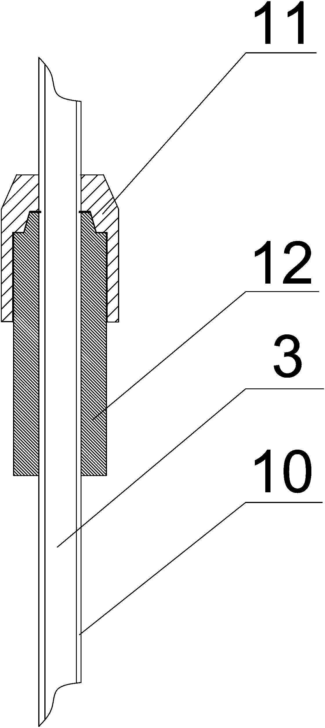
[0056] The two pliers are connected together by a connecting mechanism arranged in the center of the pliers. The connecting mechanism includes a main connecting hole 4, a secondary connecting hole 5 and a connecting shaft 6, and a slide groove 7 is arranged between the main connecting hole 4 and the secondary connecting hole 5. , wherein the inner diameter of the main connecting hole 4, the inner diameter of the auxiliary connecting hole 5 and the groove width of the chute 7 are adapted to the diameter of the connecting shaft 6 respectively; There is a second jaw 9, the inner surfaces of the first jaw 8 and the second jaw 9 are provided with serrations; the handle 3 is provide...


PUM

PropertyMeasurementUnit
tensile strengthaaaaaaaaaa
impact strengthaaaaaaaaaa

Abstract

The invention discloses an electric insulating pliers, which comprises two pliers bodies and a connecting mechanism. The pliers bodies include successively connected pliers mouths, pliers jaws and pliers handles. The pliers mouths and pliers jaws are integrally formed. The pliers handle is fixedly connected with the pliers jaw; the two pliers bodies are connected together by a connection mechanism arranged at the center of the pliers body, the connection mechanism includes a main connection hole, a secondary connection hole and a connection shaft, the main connection hole and Slide grooves are arranged between the auxiliary connecting holes. The invention solves the problems of insufficient bite force and poor insulation performance of the jaws of the existing insulating clamps.

Description

technical field [0001] The invention relates to the field of electric power maintenance equipment, in particular to an electric insulation clamp. Background technique [0002] In the process of live work, it is necessary to use various insulating tools to work away from the live body. Insulating clamps are one of the commonly used insulating tools. With the help of insulating clamps, the operator can clamp and fix the charged body from a safe distance. [0003] The Chinese patent with the authorization announcement number CN 204209573 U discloses an insulating clamp, comprising: two clamp bodies, each of which includes a jaw section, a clamp handle section and a clamp located in the jaw section and the clamp body. The pivot part between the clamp handle segments, the two pivot parts of the two clamp bodies are pivotally connected by a connecting piece, and the two jaw segments of the two clamp bodies have clamping The clamping state of the parts and the loosening state of ...

Claims


Application Information

Patent Timeline
Patent Type & Authority Patents(China)
IPC IPC(8): B25B7/10B25B7/02B25G1/12C08L27/06C08L91/00C08L9/02C08K13/02C08K5/11C08K5/12C08K5/372C08K3/34
CPCB25B7/02B25B7/10B25G1/12C08K2201/014C08L27/06C08L2205/03C08L91/00C08L9/02C08K13/02C08K5/11C08K5/12C08K5/372C08K3/346
Inventor 王坤李成彦李宴都王欢庄严马洪举张汶卓马建波张继凯全晓王海涛赵炎辉陈鹏尹应军王添张义强胡新泉王峰杨子垲段君丽
Owner NANYANG POWER SUPPLY COMPANY OF STATE GRID HENAN ELECTRIC POWER
Why Eureka
Try Eureka