Shock absorption type trolley travelling system
A walking device and trolley technology, applied in the direction of power devices, vehicle springs, vehicle parts, etc., can solve problems affecting the efficiency of frame processing and production, damage to precision components, vibration or bumping of workpieces, etc., and achieve simple structure and reliable operation , the effect of reducing the workload
- Summary
- Abstract
- Description
- Claims
- Application Information
AI Technical Summary
Problems solved by technology
Method used
Image
Examples
Embodiment 1
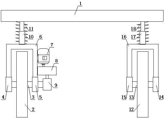
[0014] Such as figure 1 Shown, a kind of shock-absorbing trolley walking device, it comprises loading platform 1, and the bottom of described loading platform 1 is respectively provided with driving wheel 2 and driven wheel 12, and the center of described driving wheel 2 is provided with rotating shaft A3, The two ends of the rotating shaft A3 are respectively located in the bearing seat A4 and the bearing seat B5, the top of the bearing seat A4 and the bearing seat B5 is provided with a support frame A6, and the right end side wall of the support frame A6 is provided with a Motor 7, the output shaft of described motor 7 is connected with the input shaft of reduction box 8, and the output shaft of described reduction box 8 is connected the right end of rotating shaft A3 through coupling 9, and the top of described support frame A6 and loading A spring A11 is arranged between the bottom of the platform 1, a hydraulic rod A10 is arranged inside the spring A11, a rotating shaft B...
Embodiment 2
[0017] Such as figure 1 Shown, a kind of shock-absorbing trolley walking device, it comprises loading platform 1, and the bottom of described loading platform 1 is respectively provided with driving wheel 2 and driven wheel 12, and the center of described driving wheel 2 is provided with rotating shaft A3, The two ends of the rotating shaft A3 are respectively located in the bearing seat A4 and the bearing seat B5, the top of the bearing seat A4 and the bearing seat B5 is provided with a support frame A6, and the right end side wall of the support frame A6 is provided with a Motor 7, the output shaft of described motor 7 is connected with the input shaft of reduction box 8, and the output shaft of described reduction box 8 is connected the right end of rotating shaft A3 through coupling 9, and the top of described support frame A6 and loading A spring A11 is arranged between the bottom of the platform 1, a hydraulic rod A10 is arranged inside the spring A11, a rotating shaft B...
PUM
 Abstract
Description
Claims
Application Information
 - R&D
- Intellectual Property
- Life Sciences
- Materials
- Tech Scout
- Unparalleled Data Quality
- Higher Quality Content
- 60% Fewer Hallucinations
Browse by: Latest US Patents, China's latest patents, Technical Efficacy Thesaurus, Application Domain, Technology Topic, Popular Technical Reports.
© 2025 PatSnap. All rights reserved.Legal|Privacy policy|Modern Slavery Act Transparency Statement|Sitemap|About US| Contact US: help@patsnap.com

