Novel rotor aerodynamic structure for unmanned aerial vehicle

A technology of aerodynamics and rotors, applied in the directions of rotorcraft, motor vehicles, unmanned aerial vehicles, etc., can solve the problems of aircraft endurance, insufficient wing lift, high wing noise, etc., and achieve strong endurance. , The effect of high blade lift and low noise

Inactive Publication Date: 2017-01-04
成都翼高九天科技有限公司
View PDF9 Cites 10 Cited by
  • Summary
  • Abstract
  • Description
  • Claims
  • Application Information

AI Technical Summary

Problems solved by technology

[0004] The technical problem to be solved by the present invention is that the lift produced by the wing is insufficient when the traditional unmanned aircraft maintains normal flight, and the noise generated by the wing is relatively large at the same time. Insufficient lift of the drone's wings affects the endurance of the aircraft and the problem of high noise

Method used


Image

  • Novel rotor aerodynamic structure for unmanned aerial vehicle
  • Novel rotor aerodynamic structure for unmanned aerial vehicle
  • Novel rotor aerodynamic structure for unmanned aerial vehicle

Examples


Embodiment 1

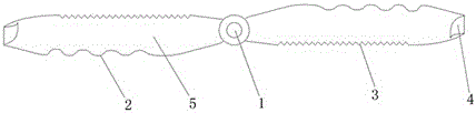
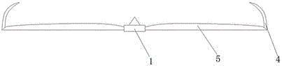
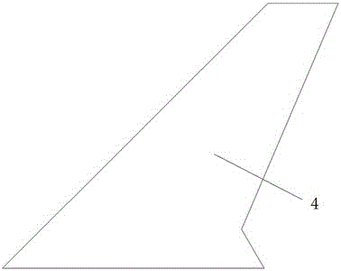
[0021] like Figures 1 to 3 As shown, a novel unmanned aerial vehicle rotor aerodynamic structure comprises a rotor shaft 1 and a blade 5 with a length of 20 cm connected to the rotor shaft 1. The leading edge 2 of the blade 5 is a sine wave structure with a wavelength of 0.1 times the length of the blade 5, the amplitude is 0.9 times the wavelength, the trailing edge 3 of the blade is a sawtooth structure of an isosceles right triangle, and the chord length of the triangle is 0.025 times the length of the blade 5, the length of the blade is The end is provided with a winglet 4, and the winglet 4 is vertically installed at the end of the blade. The winglet 4 is a swept wing and bends toward the inside of the blade, with a sweep angle of 30 degrees and a height of 0.2 times that of the blade 5. According to the experiment, the lift of the rotor using this type of blade 5 is increased by 10% and the noise is reduced by 8% when the speed is the same.

Embodiment 2

[0023] The difference between this embodiment and Embodiment 1 is that the wavelength is 0.125 times the length of the blade 5, the amplitude is 0.75 times the wavelength, the triangular chord length of the triangular sawtooth structure is 0.02 times the length of the blade 5, and the wing tip is small. The sweep angle of the wing 4 is 35 degrees, and the height is 0.225 times the length of the blade 5. According to experiments, the lift of the rotor using this type of blade 5 is increased by 13% and the noise is reduced by 10% when the speed is the same.

Embodiment 3

[0025] The difference between this embodiment and Embodiment 1 is that the wavelength is 0.1125 times the length of the blade 5, the amplitude is 0.6 times the wavelength, the triangular chord length of the triangular sawtooth structure is 0.0225 times the length of the blade 5, and the winglet The sweep angle of 4 is 40 degrees, and the height is 0.25 times the length of the blade 5. According to experiments, when the rotor using this type of blade 5 is at the same speed, the lift is increased by 12%, and the noise is reduced by 11%.


PUM


Abstract

The invention discloses a novel rotor aerodynamic structure for an unmanned aerial vehicle. The novel rotor aerodynamic structure comprises a rotor shaft and blades connected with the rotor shaft. The front edge of each blade is in a sine wave structure, the tail edge of each blade is in an isosceles right triangle shaped sawtooth structure, and the tail end of each blade is provided with a winglet which is perpendicularly mounted at the tail end of the corresponding blade. By the winglets mounted at tips of the blades respectively, streaming around of air on upper and lower surfaces can be inhibited, induced drag caused by wingtip vortexes is reduced, lift force damages caused by streaming around are reduced, lift-drag ratio is increased, and accordingly lift force is increased; in addition, due to adoption of the sine wave structured front edges and the sawtoothed rear edges according to a bionic design, low air resistance and low noise are realized. The novel rotor aerodynamic structure for the unmanned aerial vehicle has advantages of high lift force of the blades, high cruising power and low air resistance and noise in operation.

Description

technical field [0001] The invention relates to a UAV component, in particular to a novel UAV rotor aerodynamic structure. Background technique [0002] Unmanned aircraft, referred to as "drone" for short, and "UAV" for English abbreviation, is an unmanned aircraft controlled by radio remote control equipment and its own program control device. From a technical point of view, it can be divided into: unmanned fixed-wing aircraft, unmanned vertical take-off and landing aircraft, unmanned airship, unmanned helicopter, unmanned multi-rotor aircraft, unmanned parawing aircraft, etc. According to the application field, UAV can be divided into military and civilian. In terms of military use, UAVs are divided into reconnaissance aircraft and target aircraft. In terms of civilian use, drones + industry applications are the real rigid needs of drones; currently, they are used in aerial photography, agriculture, plant protection, selfies, express delivery, disaster rescue, wildlife o...

Claims


Application Information

Patent Timeline
Patent Type & Authority Applications(China)
IPC IPC(8): B64C27/467
CPCB64C27/467B64U10/25
Inventor 司佳佩
Owner 成都翼高九天科技有限公司
Why Eureka
Try Eureka