
Upper and lower board system for automatic inspection of printed circuit boards

A printed circuit board, fully automatic technology, applied in the direction of conveyor objects, transportation and packaging, conveyors, etc., can solve the problems of prolonging the time of board loading and unloading, affecting the detection efficiency, increasing the complexity of the operation time of the mechanical arm, etc., to achieve The effect of shortening the motion path and time and improving the detection efficiency

Active Publication Date: 2019-05-24
GUANGZHOU TAILI ELECTRICAL & MECHANICAL EQUIP CO LTD
View PDF6 Cites 2 Cited by
  • Summary
  • Abstract
  • Description
  • Claims
  • Application Information

AI Technical Summary

Problems solved by technology

The existing upper and lower board system will install the auxiliary fixture above the second AOI machine to facilitate the docking between the two circuit boards with the manipulator fixture. Although this upper and lower board system can realize the detection and coding of the circuit board, However, since the auxiliary fixture is installed above the second AOI machine, that is, on the right side of the robotic arm, to realize double-sided detection and double-sided coding of the circuit board, the mechanical rear fixture must be turned over several times, which increases the running time and rotation of the robotic arm. The complexity prolongs the loading and unloading time of each circuit board and affects the detection efficiency

Method used


Image

  • Upper and lower board system for automatic inspection of printed circuit boards
  • Upper and lower board system for automatic inspection of printed circuit boards
  • Upper and lower board system for automatic inspection of printed circuit boards

Examples


Embodiment Construction

[0020] Specific embodiments of the present invention will be described in detail below in conjunction with the accompanying drawings.

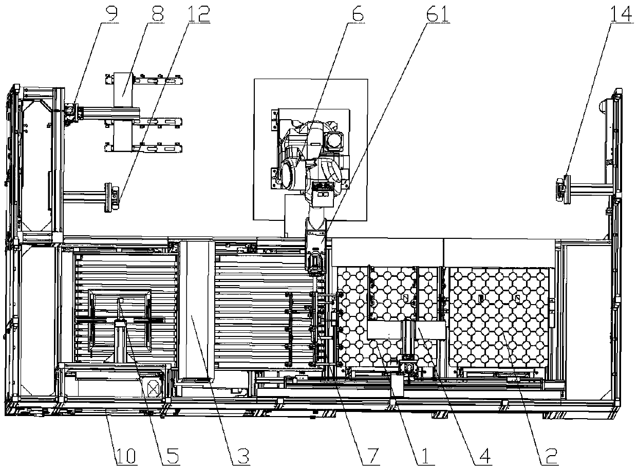
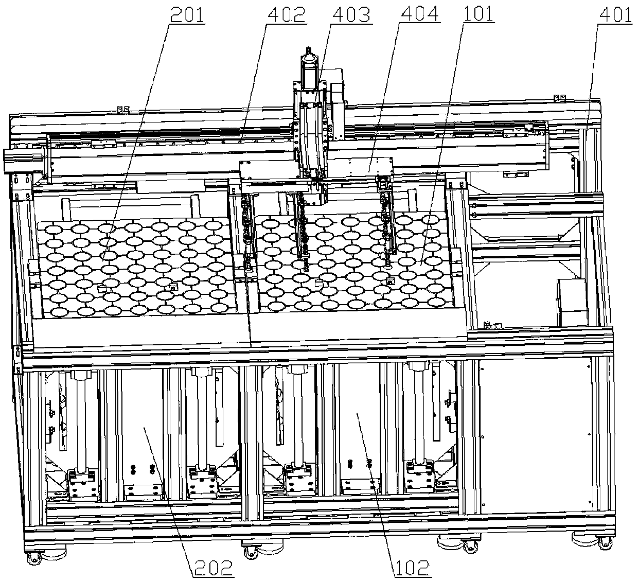
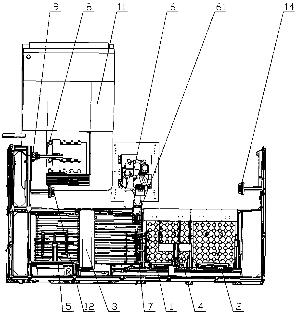
[0021] Such as figure 1 As shown, an upper and lower board system for automatic detection of printed circuit boards includes a feeding device 1, a discharging device 2, a dust sticking machine 3, a transfer device 4, an image sensor 5, a robot 6, a manipulator fixture 7, a first auxiliary The clamp 8 and the first moving mechanism 9, the feeding device 1 and the dust sticking machine 3 are arranged side by side, the transfer device 4 is set above the feeding device 1 and the dust sticking machine 3, and the image sensor 5 is set above the dust sticking machine 3 , the robot 6 is opposite to the feeding device 1 and the dust sticking machine 3, the manipulator clamp 7 is installed on the front end of the mechanical arm 61 of the robot 6, and the first auxiliary clamp 8 is arranged on the left side of the robot and passed through the first movin...


PUM


Abstract

The invention discloses a board feeding and discharging system for full-automatic detection of a printed circuit board. The board feeding and discharging system comprises a feeding device, a discharging device, a dust sticking machine, a transfer device, a robot, a mechanical arm clamp, a first auxiliary clamp and a first movement mechanism. The feeding device and the dust sticking machine are arranged side by side. The transfer device is arranged above the feeding device and the dust sticking machine. The robot is opposite to the feeding device and the dust sticking machine. The mechanical arm clamp is mounted at the front end of a mechanical arm of the robot. The first auxiliary clamp is arranged on the left side of the robot and moves in the vertical direction through the first movement mechanism. The discharging device is arranged on the right side of the robot. The auxiliary clamp is mounted on the left side of the mechanical arm and cooperates with the mechanical arm clamp, and therefore the mechanical arm can complete board feeding and discharging of one period simply by turning over the mechanical arm clamp two times, the motion path and time of the mechanical arm are shortened, and the detection efficiency of a whole detection system is improved.

Description

technical field [0001] The invention relates to an upper and lower board system for automatic detection of printed circuit boards, belonging to the technical field of auxiliary detection equipment for printed circuit boards. Background technique [0002] At present, in the process of printed circuit board processing and production, the printed circuit board automatic detection system needs to perform double-sided detection and inkjet processing on each printed circuit board. Most of the automatic inspection systems for printed circuit boards are composed of two automatic optical inspection machines (AOI), two inkjet printers, and upper and lower board systems. After the detection of side A, the first inkjet printer will spray the code on the A side of the circuit board. The second AOI machine detects the B side of the circuit board, and then the second inkjet printer performs coding on the B side of the circuit board, and then the upper and lower board systems move the circ...

Claims


Application Information

Patent Timeline
Patent Type & Authority Patents(China)
IPC IPC(8): B65G47/90
CPCB65G47/901B65G2201/022
Inventor 孙雪峰王明道张艳婷黄利明
Owner GUANGZHOU TAILI ELECTRICAL & MECHANICAL EQUIP CO LTD
Learn More