Chemical liquid bottle and manufacturing method thereof

A liquid medicine bottle and bottleneck technology, which is applied in the field of medicine liquid bottle and its manufacturing, can solve problems such as difficult sterilization process, low production efficiency, and impact on sterility, so as to save multiple processes, improve production efficiency, and reduce production cost effect

Active Publication Date: 2017-01-04
德旺国际医药投资有限公司
View PDF10 Cites 3 Cited by
  • Summary
  • Abstract
  • Description
  • Claims
  • Application Information

AI Technical Summary

Problems solved by technology

Due to the separate design of the bottle and bottle cap, in the current production process of the liquid medicine or reagent, the liquid medicine or reagent is usually filled into a pre-made bottle, then sterilized, and then sealed and screwed. Re-sterilization, so that the filling of liquid medicine or reagent requires multiple processes, and the transfer of each process will inevitably affect the sterility, and it is difficult to achieve complete sterilization in the sterilization process. Therefore, due to the multi-process As a result, the sterility of the current liquid medicine or reagent filling is relatively low, and it is difficult to meet the increasingly stringent sterility requirements
[0003] In addition, since the current filling of liquid medicine or reagent requires multiple processes of bottle making, filling, sterilization, sealing, capping, and sterilization, the process is more complicated, the production efficiency is low, and the production cost is also high.

Method used


Image

  • Chemical liquid bottle and manufacturing method thereof
  • Chemical liquid bottle and manufacturing method thereof
  • Chemical liquid bottle and manufacturing method thereof

Examples


Embodiment Construction

[0022] Further description will be given below in conjunction with the accompanying drawings and preferred embodiments of the present invention.

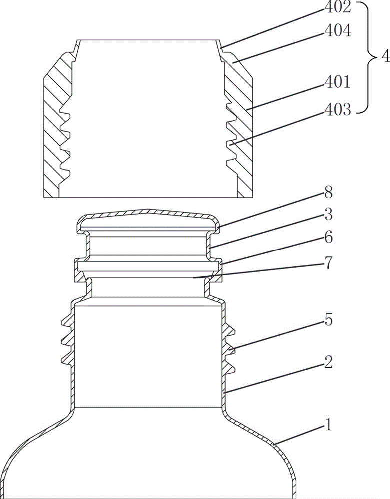
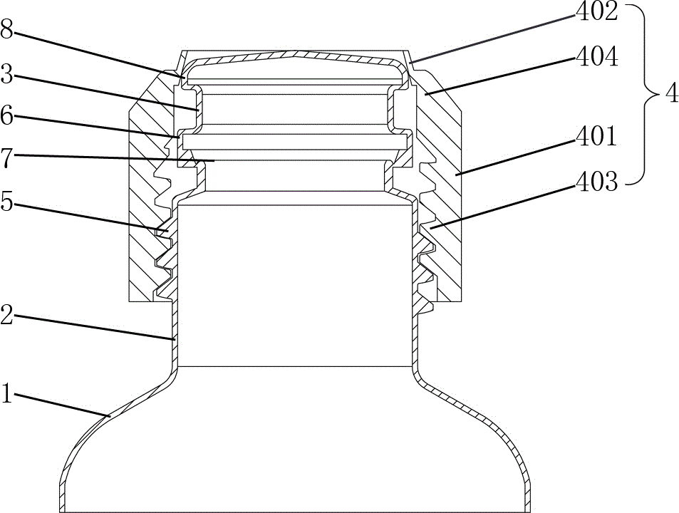
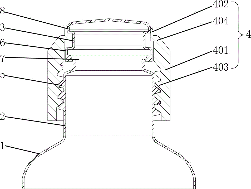
[0023] Such as figure 1 , figure 2 , Figure 6 As shown, this liquid medicine bottle includes a bottle body 1 made of plastic, a bottleneck 2, a sealing end cap 3 and a screw sleeve 4; the bottleneck 2 is arranged on the upper end of the bottle body 1, and the outer surface of the bottleneck 2 is provided with external threads 5. The lower end of the sealing end cap 3 protrudes outward to form an annular connecting portion 6, the sealing end cap 3 is connected to the upper end of the bottle neck 2 through its annular connecting portion 6, and an annular cut line 7 is provided between the sealing end cap 6 and the bottle neck 2 The bottle body 1, the bottleneck 2, and the sealing end cap 3 are integrally blow-molded; the upper end of the sealing end cap 3 is provided with an outwardly protruding annular convex portion 8; body 401...


PUM


Abstract

A chemical liquid bottle comprises a bottle body, a bottle neck, a sealing end cover and a spiral sleeve. An external thread is arranged on the outer surface of the bottle neck. The sealing end cover is connected to the upper end of the bottle neck. An annular shear mark line is arranged between the sealing end cover and the bottle neck. The bottle body, the bottle neck and the sealing end cover are formed integrally through blow molding. An annular protruding part which protrudes outwards is arranged at the upper end of the sealing end cover. The bottle neck is sleeved with the spiral sleeve. The spiral sleeve comprises an annular sleeve body and a supporting ring. An internal thread is arranged in the annular sleeve body. The supporting ring is connected to the upper end of the annular sleeve body. A plurality of longitudinal clamping seams are formed in the supporting ring. The outer diameter of the lower end of the sealing end cover and the outer diameter of the annular protruding part are both larger than the inner diameter of the supporting ring. A bottle cap is detached into the spiral sleeve and the sealing end cover, so that the sealing end cover, the bottle body and the bottle neck are formed integrally through blow molding, the spiral sleeve and the sealing end cover are combined to form the bottle cap only in the detaching process, the chemical liquid filling efficiency is improved, the production cost is reduced, the sterility of filled chemical liquid is higher, and high sterility of the chemical liquid can be maintained in the using process.

Description

technical field [0001] The invention relates to a packaging bottle, in particular to a liquid medicine bottle and a manufacturing method thereof. Background technique [0002] During the filling process of medical liquids or reagents, the requirements for sterility are very high and must be carried out in a sterile environment. Due to the separate design of the bottle and bottle cap, in the current production process of the liquid medicine or reagent, the liquid medicine or reagent is usually filled into a pre-made bottle, then sterilized, and then sealed and screwed. Re-sterilization, so that the filling of liquid medicine or reagent requires multiple processes, and the transfer of each process will inevitably affect the sterility, and it is difficult to achieve complete sterilization in the sterilization process. Therefore, due to the multi-process As a result, the sterility of liquid medicine or reagent filling is relatively low at present, and it is difficult to meet th...

Claims


Application Information

Patent Timeline
Patent Type & Authority Applications(China)
IPC IPC(8): B67C7/00B65D51/18B65D41/34
CPCB65D41/34B65D51/18B67C7/00
Inventor 李建德吴琏
Owner 德旺国际医药投资有限公司
Why Eureka
Try Eureka