Novel steel-concrete composite bridge and construction method thereof

A concrete and bridge technology, applied in the direction of bridges, bridge parts, bridge construction, etc., can solve problems such as urban traffic congestion, achieve the effect of novel materials, excellent quality, and solve the problem of urban traffic congestion

Active Publication Date: 2017-01-04
WUHAN UNIV OF TECH
View PDF6 Cites 16 Cited by
  • Summary
  • Abstract
  • Description
  • Claims
  • Application Information

AI Technical Summary

Problems solved by technology

[0006] The purpose of the present invention is to provide a new type of steel-concrete composite bridge and its construction method, improve the overall m

Method used


Image

  • Novel steel-concrete composite bridge and construction method thereof
  • Novel steel-concrete composite bridge and construction method thereof
  • Novel steel-concrete composite bridge and construction method thereof

Examples


Embodiment 1

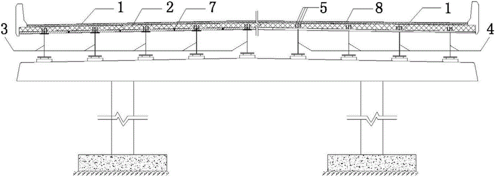
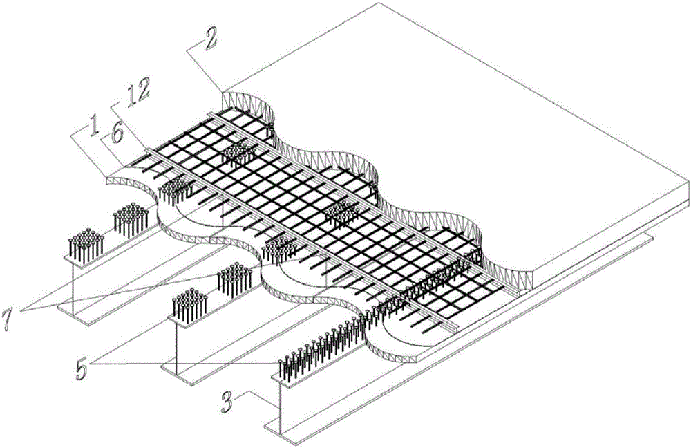
[0044] Such as figure 1 , 2 , 4-6, a new type of steel-concrete composite bridge, including the main girder, cast-in-place SAP internal curing concrete bridge deck 2 and shear nails 5. The main girder is formed by connecting the I-shaped steel beam 3 and the FRP plate 1, the upper flange plate of the I-shaped steel beam 3 is provided with shear nails 5, the FRP plate 1 is located on the top surface of the I-shaped steel beam 3, and the FRP plate 1 It is fixed by shear nails 5 and I-beam 3. A number of main girders (for example, 3 to 20 pieces) are assembled and erected along the transverse direction of the bridge, and all the main girders are connected by end connecting plates 11 along the longitudinal direction of the bridge to form a whole (the whole is formed by anchoring bolts of the end connecting plates along the longitudinal direction of the bridge to form a whole), forming a multi-hole joint. (the length of the porous primary girder is the bridge length between two a...

Embodiment 2

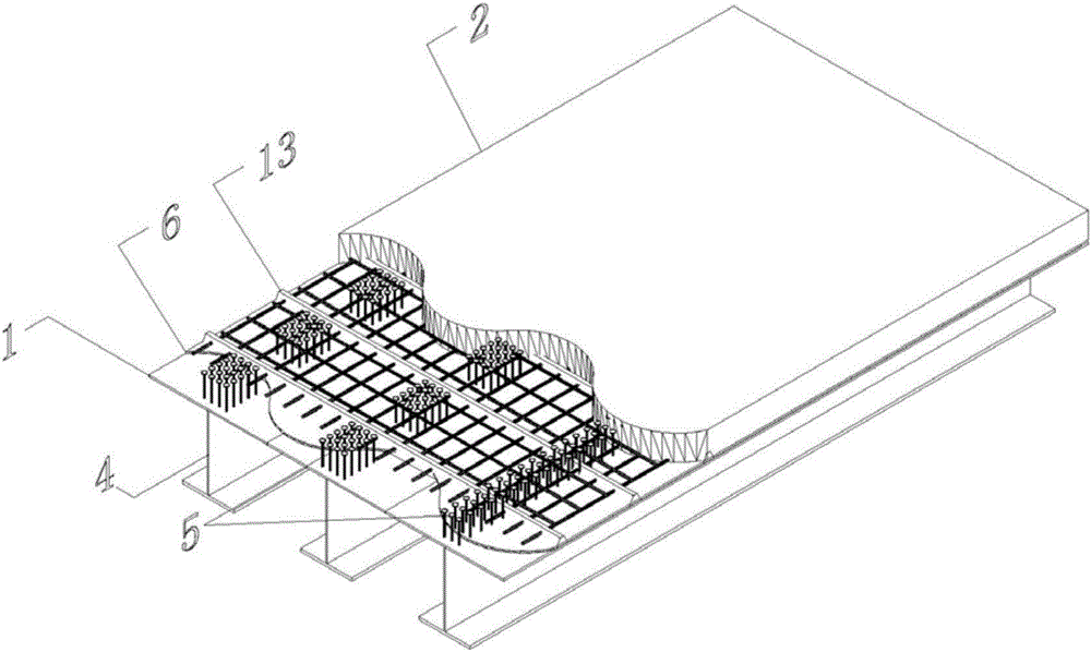
[0062] Such as figure 1 , 3 , 4-6, a new type of steel-concrete composite bridge, including the main girder, cast-in-place SAP internal curing concrete bridge deck 2 and shear nails 5. The main girder is a T-shaped steel girder 4, and the upper flange steel plate of the T-shaped steel girder 4 is provided with shear studs 5. The prefabricated T-shaped steel girder 4 is the main girder structure, and the whole is hoisted and placed on the temporary support 10, and several pieces (such as 3 to 20 pieces) are assembled and erected along the transverse bridge direction, and connected in sequence along the longitudinal direction of the bridge through the end connecting plate 11, The longitudinal seams of the upper flange steel plates (steel plates) of the T-shaped steel beam 4 are welded to form a whole prefabricated main girder to form a porous joint (the length of the porous single joint main girder is the length of the bridge between two adjacent expansion joints), Such as i...


PUM

PropertyMeasurementUnit
Thicknessaaaaaaaaaa
Thicknessaaaaaaaaaa
Diameteraaaaaaaaaa

Abstract

The invention relates to a steel-concrete composite bridge and a construction method thereof. The novel steel-concrete composite bridge is characterized by comprising main beams, a cast-in-situ SAP (Super Absorbent Polymer) internal curing concrete bridge panel and shear studs, wherein clustered or uniformly-distributed shear studs are arranged on the main beams; a plurality of main beams are erected in a splicing way along the transverse direction of the bridge; all the main beams are connected into a whole through an end connecting plate along the longitudinal direction of the bridge, thereby forming a multi-hole connection structure; the top surfaces of the main beams are provided with open stiffening ribs, and are coated with an epoxy resin bonding layer; an SAP is poured on the epoxy resin bonding layer to realize internal curing; a cast-in-situ SAP internal curing concrete bridge panel is formed by concrete; the shear studs, longitudinal and transverse reinforcing meshes and the open stiffening ribs are positioned in the cast-in-situ SAP internal curing concrete bridge panel. An FRP (Fiber Reinforced Polymer/Plastic) board or an upper flange steel board of a T-shaped steel beam is a template which is light, has high strength and high stress performance and does not need to be detached; SAP internal curing concrete has a weak shrinking and gradual changing effect, so that the problem of tendency to cracking when the conventional concrete bridge panel is too large and too thin is solved; the influence of floor stand construction on urban traffic is lowered remarkably.

Description

technical field [0001] The invention relates to a steel-concrete composite bridge and a construction method thereof. Background technique [0002] At present, with the continuous increase of urban supersaturated traffic volume, urban viaducts have developed rapidly. As an important link in urban three-dimensional transportation, viaducts can significantly relieve traffic pressure, save urban space, improve people's quality of life, and promote rapid urban development. Traditional urban viaducts are mainly made of (prestressed) reinforced concrete beams, which are heavy and have a long construction period. On-site pouring will inevitably bring serious traffic congestion problems; in recent years, steel bridges have gradually developed, with light weight and convenient construction. It is difficult to overcome the diseases such as the shifting and wrapping of the pavement layer, and the high construction cost seriously hinders its development and application. However, the stee...

Claims


Application Information

Patent Timeline
IPC IPC(8): E01D1/00E01D19/00E01D21/00
CPCE01D1/00E01D19/00E01D21/00
Inventor 刘沐宇李倩张强高宗余丁庆军卢志芳邓晓光刘云鹏
Owner WUHAN UNIV OF TECH
Why Eureka
Try Eureka