

Oil pump of compressor and variable frequency compressor
A technology for compressors and oil pumps, applied in the field of compressors, can solve the problems of high installation space requirements, high oil storage requirements, complex installation layout structures, etc., and achieve the effect of avoiding load increase
- Summary
- Abstract
- Description
- Claims
- Application Information
AI Technical Summary
Problems solved by technology
Method used
Image

Examples
Embodiment 1
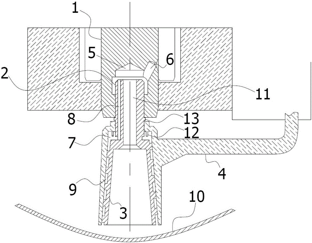
[0064] In the optional scheme of this embodiment, such as figure 1 As shown, further, the lower oil delivery hole 9 is a spiral hole formed by the cooperation between the inner wall of the pump sleeve 4 and the spiral groove provided on the outer wall of the lower mandrel 3 . In this embodiment, the spiral hole is formed by the cooperation between the inner wall of the pump sleeve 4 and the spiral groove provided on the outer wall of the lower mandrel 3. When the lower mandrel 3 rotates, the helical hole can lift the lubricating oil in the oil pool 10 upwards, And at low speed, the oil can be delivered to a higher position.
[0065] In the optional scheme of this embodiment, such as figure 1 As shown, further, the shape of the lower mandrel 3 is a circular truncated body, the diameter of its upper end surface is smaller than the diameter of its lower end surface, and the inner wall of the pump sleeve 4 fits the outer wall of the lower mandrel 3; while the pump sleeve 4 floats...
Embodiment 2
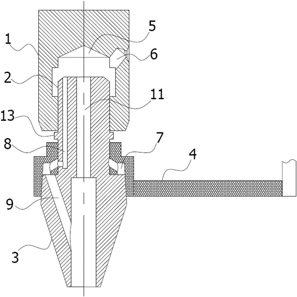
[0067] In the optional scheme of this embodiment, such as figure 2 As shown, further, the lower oil delivery hole 9 is arranged obliquely, communicating with the annular cavity 7 and the oil pool 10 . The lower oil delivery hole 9 is arranged in the lower mandrel 3 body to form a certain inclination angle with the vertical mandrel axis, then the lubricating oil in the oil pool 10 can be introduced into the annular cavity 7 by centrifugal force when the mandrel rotates. The oil pump in this structural form reduces the agitation of the lubricating oil by the part of the outer wall of the lower mandrel 3 immersed in the oil pool, thereby reducing energy consumption and noise.
[0068] In the alternatives of the first and second embodiments, further, an annular groove or a blind hole is provided on the side wall of the slot 5 of the crankshaft 1 . In this embodiment, due to the interference fit between the upper mandrel 2 and the slot hole 5, the elasticity of the material of th...
PUM
 Abstract
Description
Claims
Application Information