
Combined grate plate structure

A grate piece and combined technology, applied in the direction of incinerator, combustion type, combustion method, etc., can solve the problems of shortening downtime, achieve the effect of shortening downtime, solving the problem of uneven wear, and improving the operation rate of equipment

Active Publication Date: 2017-01-04
NANJING KISEN INT ENG
View PDF7 Cites 0 Cited by
  • Summary
  • Abstract
  • Description
  • Claims
  • Application Information

AI Technical Summary

Problems solved by technology

[0008] The positive effect of the present invention: in the technical solution of the present invention, by applying a combined grate piece on the incineration grate furnace, the maintenance and labor costs of the grate piece are saved; The problem of uneven wear of the grate improves the overall service life of the grate; the application of the grate sheet shortens the downtime and improves the operation rate of the equipment

Method used


Image

  • Combined grate plate structure
  • Combined grate plate structure
  • Combined grate plate structure

Examples


Embodiment Construction

[0027] In order to make the object, technical solution and advantages of the present invention clearer, the present invention will be further described in detail below in conjunction with specific implementation methods and accompanying drawings. Here, the exemplary embodiments of the present invention and their descriptions are used to explain the present invention, but not to limit the present invention.

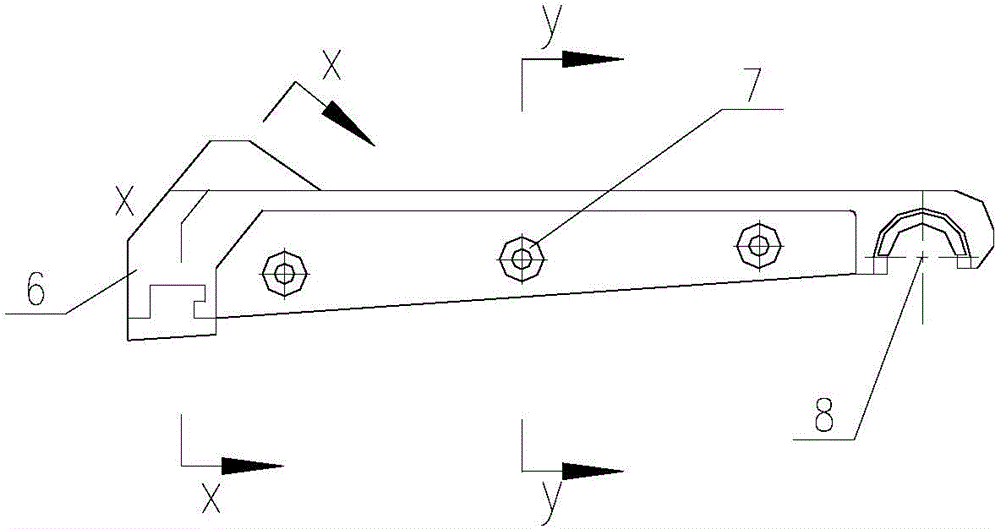
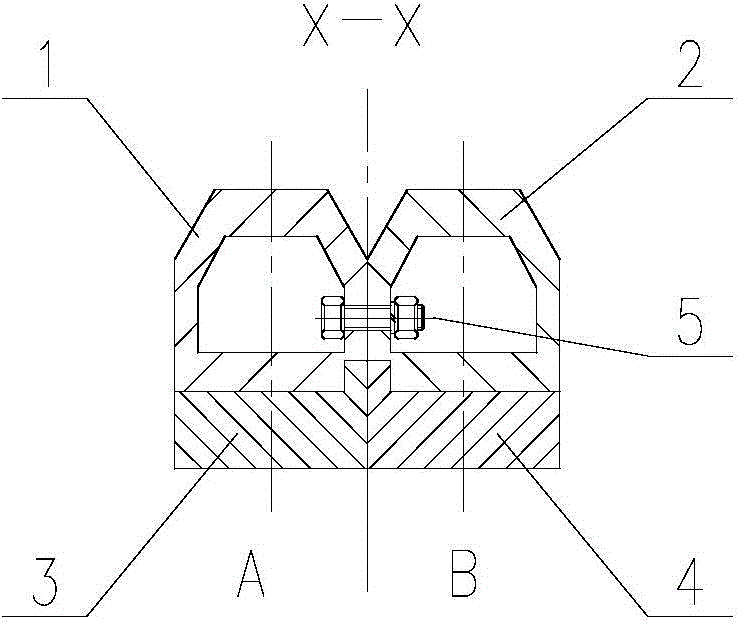
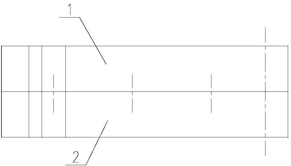
[0028] Such as Figure 1-Figure 12 As shown, the combined grate structure of the present invention includes A-side grate 1, B-side grate 2, A-side insert 3, B-side insert 4, and positioning piece 5; A-side grate 1 and B-side furnace The grate 2 is a matching assembly; the A-side grate 1 and the B-side grate 2 are also equipped with a tail support hole 8; the A-side insert 3 has a concave-convex bayonet 11, and is installed on the A-side grate 1 The head 6 slot of the side B; the B-side insert 4 has a concave-convex bayonet 11, and is installed in the head 6 slot of the B-...


PUM


Abstract

The invention relates to incineration equipment, particularly to a combined grate plate structure which is mainly used for incinerating unclassified low-calorific value and high-moisture household garbage. The combined grate plate structure comprises an A-side grate plate, a B-side grate plate, an A-side embedded block, a B-side embedded block and a locating piece. In the technical scheme, the A-side grate plate, the B-side grate plate, the A-side embedded block, the B-side embedded block and the locating piece are combined and mounted into a combined grate plate, so that the mounting and maintenance of a grate are facilitated, the maintenance cost of the grate plate is reduced, and redundant equipment input and labor waste are avoided; the thickness of the embedded blocks is set in different zones, so that the problem that abrasion of the grate is nonuniform is solved, and the entire service life of the grate is prolonged; and through the design of included angles of bevels of the embedded blocks, small sundries clamped in a motion gap of the grate successfully fall off, the service life of the grate plate is prolonged, the downtime of an incinerator is shortened, and the running rate of the equipment is increased.

Description

technical field [0001] The invention relates to an incineration device, in particular to a combined fire grate structure mainly used for incinerating low calorific value, high moisture and unsorted domestic waste. Background technique [0002] Aiming at the problem of municipal solid waste disposal, the more effective treatment method at present is the incineration method, which is also the garbage disposal method generally adopted by countries all over the world. The incineration equipment used in many countries and my country is the grate type incinerator. The grate type incinerator has the advantages of low pretreatment requirements for waste, wide range of heat value for waste, and easy operation and maintenance. The key combustion equipment is the grate, which is generally made of high-chromium-molybdenum alloy, heat-resistant, wear-resistant, and corrosion-resistant cast steel, and its material performance and structure are relatively unique. [0003] The service life...

Claims


Application Information

Patent Timeline
IPC IPC(8): F23G5/44
Inventor 徐连春陈新平徐靖
Owner NANJING KISEN INT ENG
Learn More