Current detecting circuit based on bi-directional saturation current sensor and driving method thereof

A technology of current detection circuit and current sensor, which is applied in the direction of measuring current/voltage, only measuring current, instruments, etc., can solve the problem that the detection current temperature has a large influence and it is difficult to meet the reliable high-temperature working ability and high-precision isolation of SiC-based high-temperature resistant converters. And AC/DC detection ability, Hall element is difficult to withstand high temperature environment above 200 ℃, etc.

Inactive Publication Date: 2017-01-04
NANJING UNIV OF AERONAUTICS & ASTRONAUTICS
View PDF3 Cites 5 Cited by
  • Summary
  • Abstract
  • Description
  • Claims
  • Application Information

AI Technical Summary

Problems solved by technology

The Hall effect sensor is based on a Hall-type device located in the air gap of the magnetic core to detect DC or tens of kHz AC components, but the Hall element is difficult to withstand a high temperature environment above 200°C.
[0006] Summarizing the above current detection methods, it can be seen that the current detection methods of Si-based converters are difficult to meet the reliable high-temperature working ability, high precision, low loss, isolation and AC / DC detection capabilities of SiC-based high-temperature converters.
The current sensor made of magnetic ring can meet the requirements of SiC-based high-temperature resistant converters. The coercive force of the ideal magnetic element is zero, but the remanence and coercive force of the magnetic material of the actual current sensor will cause errors in the detection current, which need to be eliminated. Effect of Coercive Force Hc on Detection Current
In addition, the B-H curve of the magnetic material drifts with the temperature, so that the detection current is greatly affected by the temperature, so it is necessary to compensate the temperature difference for the detection current

Method used


Image

  • Current detecting circuit based on bi-directional saturation current sensor and driving method thereof
  • Current detecting circuit based on bi-directional saturation current sensor and driving method thereof
  • Current detecting circuit based on bi-directional saturation current sensor and driving method thereof

Examples


Embodiment

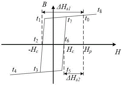
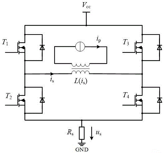
[0038] The operating principle of the circuit of the present invention is: the primary side current i p and primary magnetic field strength H p The relationship is: H p =(i p ·N p ) / l m ; H-bridge power device T 1 , T 4 Secondary current i at turn-on s1 , T 2 , T 3 Secondary current i at turn-on s2 The relationship with the magnetic field strength of the secondary side is: ΔH s1 =(i s1 ·N s ) / l m , ΔH s2 =(i s2 ·N s ) / l m . It can be seen from the hysteresis loop of the secondary side of the current sensor: H p =(ΔH 1 +ΔH 2 ) / 2. Therefore, the source current to be measured can be represented by two secondary currents: i p =N s (i s1 + i s2 ) / 2N p .

[0039] From the hysteresis loop of the secondary side of the current sensor, it can be seen that the remanence of the positive half axis and the negative half axis are H c and -H c . When the temperature rises, the size of the positive and negative remanence will drift with temperature, but the magnit...


PUM


Abstract

The invention discloses a current detecting circuit based on a bi-directional saturation current sensor and a driving method thereof. The current detecting circuit is composed of a magnetic ring current sensor, an H-bridge current detecting circuit and a bridge arm power device driving circuit. The current sensor is used for achieving a high-temperature-resistant operational capability and an isolation function. The H-bridge current detecting circuit makes the secondary side of the current sensor bidirectional saturation, compensates influences of positive and negative residual magnetism on current detection, and eliminates errors of the positive and negative residual magnetism along with temperature drift. A comparator and a D trigger are used for achieving rapid response. Compared with a conventional current detecting circuit, the current detecting circuit of the invention has a high-temperature-resistant operational capability, an isolation function, fast response and high precision, and is suitable for detecting the current of high-temperature-resistant motor driver based on SiC MOSFETs.

Description

technical field [0001] The invention relates to a high temperature resistant current detection circuit, in particular to a high temperature resistant current detection circuit based on a bidirectional saturated current sensor. It belongs to the field of power electronics. Background technique [0002] In the control strategy of the motor driver, the switching frequency of the power device is directly derived from the sense current. Therefore, Si-based converters use current detection methods such as Hall sensors and resistor shunts to realize current detection. [0003] With the rapid development of new SiC devices, motor drivers based on SiC devices can be widely used in high-temperature applications such as electric aircraft, electric vehicles, and oil drilling, where the working environment temperature exceeds 200 °C. However, limited by the temperature, the current detection method based on the Si converter is difficult to apply to the SiC-based high temperature conver...

Claims


Application Information

Patent Timeline
Patent Type & Authority Applications(China)
IPC IPC(8): G01R19/00
CPCG01R19/0092
Inventor 谢昊天秦海鸿朱梓悦付大丰徐华娟
Owner NANJING UNIV OF AERONAUTICS & ASTRONAUTICS
Why Eureka
Try Eureka