Method for directly measuring winding loss of magnetic component

A technology of winding loss and magnetic components, applied in the field of direct measurement of winding loss of magnetic components, can solve the problems of inability to realize on-line measurement of winding loss of magnetic components in power converters and has great influence, and achieve the effect of convenient measurement and low cost

Inactive Publication Date: 2017-01-04
FUJIAN UNIV OF TECH
View PDF5 Cites 12 Cited by
  • Summary
  • Abstract
  • Description
  • Claims
  • Application Information

AI Technical Summary

Problems solved by technology

However, this method is greatly affected by the load resistance, that is, the stability of the resistance value of the load resistance, distributed inductance and frequency characteristics will seriously affect the measurement results. Therefore, the inventor of this method also recommends using low-inductance resistors as load resistance, and scale the load resistance with an impedance analyzer for accurate resistance and phase response
In addition, this measurement method can only measure the winding loss under the condition of a given excitation waveform, but it still cannot realize the online measurement of the winding loss of the magnetic element in the power converter under the real working condition

Method used


Image

  • Method for directly measuring winding loss of magnetic component
  • Method for directly measuring winding loss of magnetic component
  • Method for directly measuring winding loss of magnetic component

Examples


no. 1 example

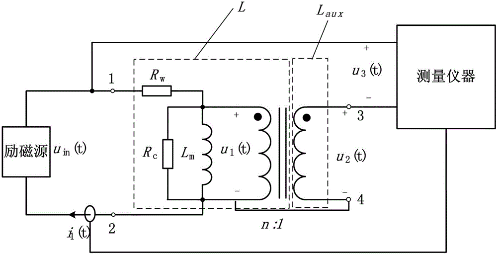
[0025] Such as figure 1 As shown, the first embodiment of the present invention aims at the measurement of the measured inductive winding loss when the turns ratio n of the measured inductive winding and the auxiliary winding is 1. For the measured inductor winding and auxiliary winding turn ratio n is 1, the measured inductor winding loss measurement. The excitation source can be composed of a signal generator and a power amplifier, or it can be the actual excitation waveform at both ends of the magnetic element in the actual power converter; L is the measured inductance, where R w Is the equivalent resistance of the measured inductor winding, which reflects the winding loss of the inductor, R c In order to reflect the equivalent resistance of the measured inductor core loss, L m Is the magnetizing inductance of the measured inductance, L aux Is the auxiliary winding, terminal 1 and terminal 2 are the two pins of the measured inductance L, terminal 3 and terminal 4 are the two p...


PUM


Abstract

The invention discloses a method for directly measuring the winding loss of a magnetic component, wherein the magnetic component includes a magnetic core and a winding. According to the method, an auxiliary winding is additionally wound on the magnetic core of the magnetic component; the auxiliary winding is open-circuited; an excitation source is applied to the magnetic component; a voltage relation between the port of the measured winding and the port of the auxiliary winding of the magnetic component, and current passing through the measured winding are measured through a measuring instrument; voltage between the ports is calculated, so that the voltage the lost of the measured winding can be obtained; and the power of the measured winding is obtained through calculation, and the power of the measured winding is the loss of the measured winding. The method of the invention is suitable for measuring the winding loss of any magnetic component under any excitation waveform condition and is also used for measuring the winding loss of a magnetic component in a power converter online. The method can embody influences on winding loss caused by a magnetic field, temperature and actual working conditions in a magnetic component and can also measure the loss of each winding of a multi-winding magnetic component. With the method adopted, winding loss can be separated from total loss. The method has the advantages of convenient measurement, quickness and low cost.

Description

Technical field [0001] The invention relates to the field of electric power and power electronic equipment, and in particular to a method for directly measuring the winding loss of a magnetic element. Background technique [0002] Magnetic components are responsible for the transmission, storage, filtering and other functions of magnetic energy. They play an extremely important role in power systems and power converters. With the development of power converters towards high frequency and high power density, the loss of magnetic components becomes a constraint One of the key factors of its development. In addition to meeting the requirements of basic electrical parameters, the loss of magnetic components has also become a key issue in the design of magnetic components, because the loss of magnetic components has accounted for a large part of the total power loss of the power converter. Especially for the energy efficiency index of the power converter, not only the total loss of t...

Claims


Application Information

Patent Timeline
Patent Type & Authority Applications(China)
IPC IPC(8): G01R27/26
CPCG01R27/2694
Inventor 叶建盈郑荣进
Owner FUJIAN UNIV OF TECH
Why Eureka
Try Eureka