Direct current power transmission line fault identification method by employing filter branch current and principal component analysis method

A technology for DC transmission lines and principal component analysis, which can be applied to fault locations, fault detection by conductor type, instruments, etc., and can solve problems such as weak anti-interference ability and insufficient sensitivity of remote high resistance.

Active Publication Date: 2017-01-04
KUNMING UNIV OF SCI & TECH
View PDF6 Cites 8 Cited by
  • Summary
  • Abstract
  • Description
  • Claims
  • Application Information

AI Technical Summary

Problems solved by technology

[0003] The technical problem to be solved by the present invention is to provide a DC transmission line fault identification method using filter branch current and principal

Method used


Image

  • Direct current power transmission line fault identification method by employing filter branch current and principal component analysis method
  • Direct current power transmission line fault identification method by employing filter branch current and principal component analysis method
  • Direct current power transmission line fault identification method by employing filter branch current and principal component analysis method

Examples


Embodiment 1

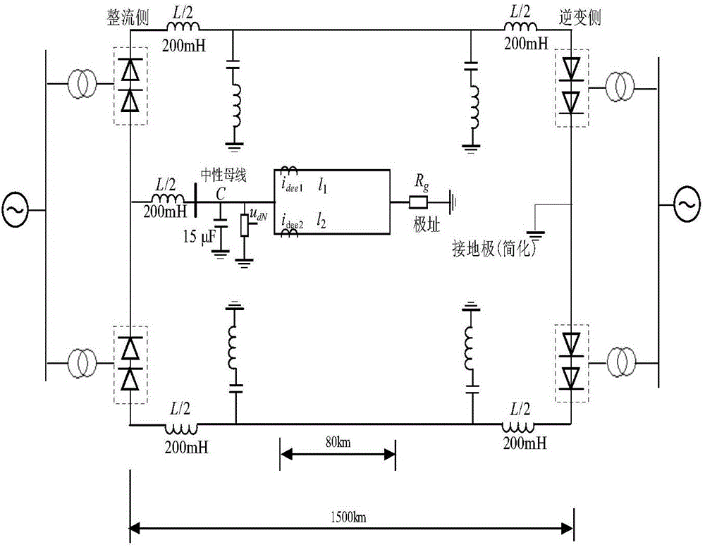
[0056] Example 1: Establish as attached figure 1 The Yun-Guang ±800kV UHV DC transmission system is shown as the simulation model. The reactive power compensation capacities of the rectifier side and the inverter side are 3000 and 3040Mvar respectively. Each pole commutation unit is composed of two 12-pulse converters connected in series. The total length of the DC transmission line is 1500km. 400mH smoothing reactors are installed on both sides of the line, and the DC filter is a 12 / 24 / 36 three-tuned filter. Now assume that the positive line is 1002km away from the Q terminal and a ground fault occurs, the transition resistance is 10Ω, and q set =-1.

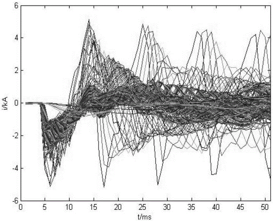
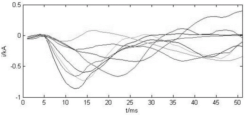
[0057] According to the first step, the sample database and its PCA clustering space are established: the faults set along the long range of the UHVDC line and the rectification side faults and inverter side faults outside the area are set, and 6 sampling points obtained by electromagnetic transient simulation The current c...

Embodiment 2

[0058] Example 2: Establish as attached figure 1 The Yun-Guang ±800kV UHV DC transmission system is shown as the simulation model. The reactive power compensation capacities of the rectifier side and the inverter side are 3000 and 3040Mvar respectively. Each pole commutation unit is composed of two 12-pulse converters connected in series. The total length of the DC transmission line is 1500km. 400mH smoothing reactors are installed on both sides of the line, and the DC filter is a 12 / 24 / 36 three-tuned filter. Now assume that the positive line is faulty from the outlet of the rectifier side, the transition resistance is 10Ω, and q set =-1.

[0059] According to the first step, the sample database and its PCA clustering space are established: the faults set along the long range of the UHVDC line and the rectification side faults and inverter side faults outside the area are set, and 6 sampling points obtained by electromagnetic transient simulation The current curve cluster ...


PUM


Abstract

The present invention relates to a direct current power transmission line fault identification method by employing a filter branch current and principal component analysis method, belonging to the electric power system protection technology field. The method comprises: firstly, building a sample database, along the full line of the UHVDC, setting a fault position for faults in an area along a line, setting fault positions at a rectification side and an inversion side for the faults out of the area, taking the filter branch current curve cluster in the six sample points obtained by the electromagnetic transient simulation as sample data to perform the PCA cluster analysis, building the PCA cluster space, and forming obviously distinguished line faults and the cluster point cluster of two fault modal out of the area; secondary, after the starting component is started, taking polar fault current data in the six sample points as test samples, calculating the test sample data, and calculating the projection value q1 of the PCA cluster space; and finally, determining whether the faults are located in the area or out of the area, and the UHVDC is configured to transmit power for the extra-high voltage direct current.

Description

technical field [0001] The invention relates to a DC transmission line fault identification method using a filter branch current and a principal component analysis method, and belongs to the technical field of power system protection. Background technique [0002] At present, the traveling wave protection is mostly used as the fast main protection for DC transmission lines, and the current differential protection is used as the slow backup protection. The traveling wave protection method mainly obtains the protection criterion by processing the current or voltage traveling wave signal. For signal acquisition, current or voltage traveling waves obtained by single-ended or double-ended lines are mostly selected at present. However, when the DC system is operating normally, a large load current flows through the DC line side. When the DC system fails, compared with the large load current, the current change before and after the fault is not obvious. The smoothing reactor and ...

Claims


Application Information

Patent Timeline
IPC IPC(8): G01R31/08
CPCG01R31/085G01R31/088Y04S10/52
Inventor 束洪春王璇杨晨曦田鑫萃
Owner KUNMING UNIV OF SCI & TECH
Why Eureka
Try Eureka