
Method for radar waveform designing and optimization

A radar waveform and waveform technology, applied in the field of radar waveform design and optimization, can solve the problems of uncontrollable signal spectrum shape, loss, difficulty in meeting the requirements of radar waveform applications, etc.

Inactive Publication Date: 2017-01-04
胡文
View PDF4 Cites 11 Cited by
  • Summary
  • Abstract
  • Description
  • Claims
  • Application Information

AI Technical Summary

Problems solved by technology

However, the signal generated by chaotic modulation does not necessarily have chaos, and the loss of chaos will cause the loss of application characteristics such as ambiguity function, orthogonality, low intercept probability and anti-interference of the signal.
The structure of the traditional classical chaotic system does not consider the radar application background, and it is difficult to meet the application requirements of the current radar waveform by using it as the signal source structure, such as low PAPR, controllable spectrum shape, high detection Waveform properties such as probability
[0004] In the patent "A Method for Radar Waveform AM and Phase Modulation Based on Mixed Sequence" (Patent No. CN 105068051 A), Zhou Yun proposed to use a compound sequence formed by mixing tent sequence and logistic sequence at 1:1 for joint AM and phase modulation waveform , thereby reducing the predictable probability of chaotic signals and the probability of radar interception, and improving the anti-jamming performance, but there are disadvantages such as high peak-to-average power ratio (PAPR) and uncontrollable spectral shape of the signal.

Method used


Image

  • Method for radar waveform designing and optimization
  • Method for radar waveform designing and optimization
  • Method for radar waveform designing and optimization

Examples


Embodiment Construction

[0024] In order to make the object, technical solution and advantages of the present invention clearer, the present invention will be further described in detail below with reference to the accompanying drawings.

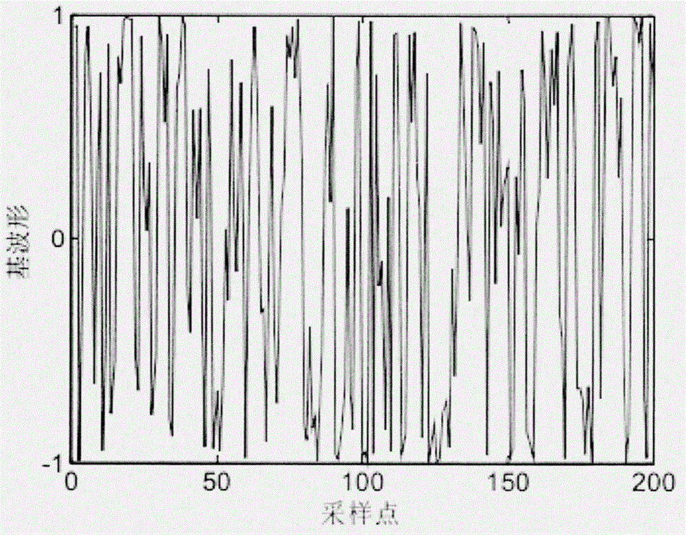
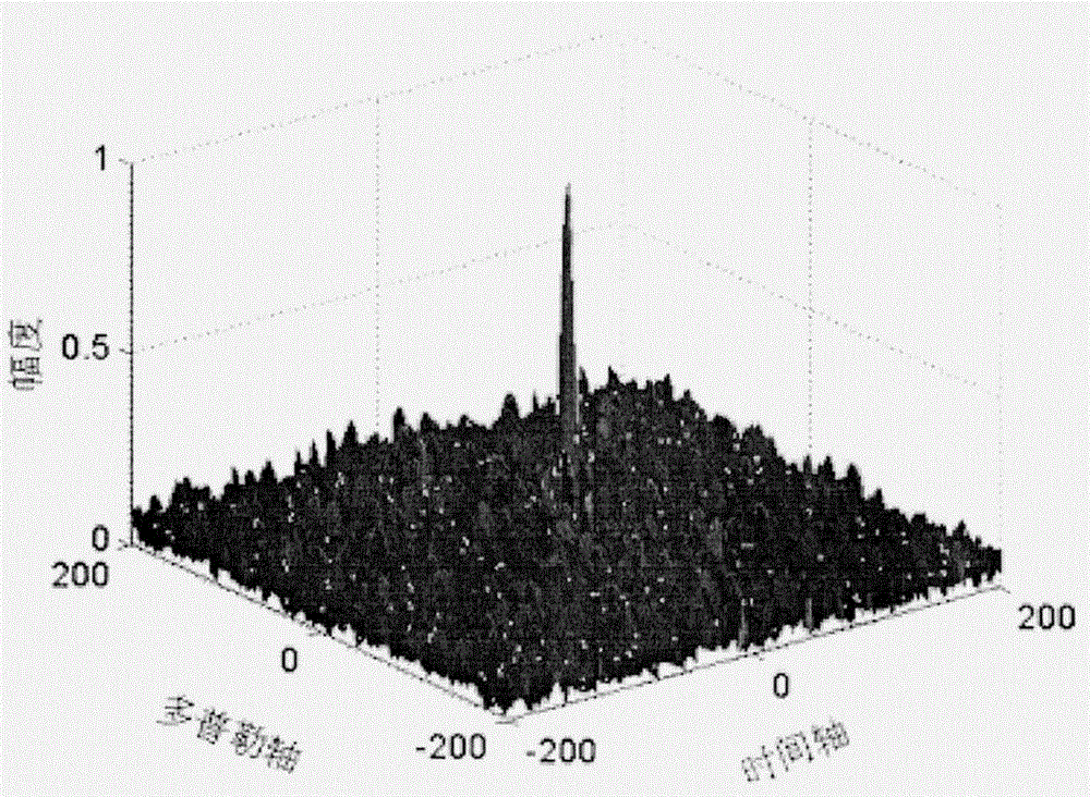
[0025] The present invention provides a radar waveform design and optimization method, the overall flow of the design is as follows figure 1 As shown, firstly, according to the requirements of radar waveform design for spectrum controllability and low peak-to-average power ratio, an optimized dictionary is designed. Furthermore, the signal generation system is composed of signal synthesis, observation matrix and sparse coefficient control in a closed-loop form. The signal synthesis generates output signals according to the dictionary and sparse coefficients. The output signal is compressed by the observation matrix, and the compressed signal is directly obtained by the sparse coefficient control system. The sparse coefficients required for the next signal synthesis....


PUM


Abstract

The invention discloses a method for radar waveform designing and optimization, wherein the method belongs to the field of radar communication technology. The invention aims to provide the method for waveform designing and optimization, wherein the waveform has characteristics of relatively good thumbtack ambiguity function, low interception probability, relatively high interference resistance, good orthogonality, relatively low peak value power ratio, controllable spectral shape, controllable signal sparsity, controllable signal reconfigurability, etc. According to the method, a related dictionary is optimized according to the requirement for spectrum controllability and low peak mean value power ration in radar waveform design. Furthermore a signal generating system is formed by a signal synthesizing part, an observation matrix part and a sparsity coefficient control part in a closed-loop manner. In signal synthesizing, an output signal is generated according to the dictionary and the sparsity coefficient; a compressed signal is obtained from an output signal through an observation matrix; and the sparsity coefficient required for signal synthesizing at next time is directly obtained from the compression signal through a sparsity coefficient control system. Then in a signal reconstruction system, a reconstructed signal is synthesized from the compressed signal according to the information of the dictionary through the sparisity coefficient control system. The method for radar waveform designing and optimization realizes relatively good application characteristic of the designed radar waveform.

Description

technical field [0001] The invention relates to a radar waveform design and optimization method, which belongs to the technical field of radar communication. Background technique [0002] Waveform design is an important direction in the research field of Radar (Radio Detection and Ranging, Radar). The main signal characteristics concerned by radar waveform design can be summarized as follows: pushpin-type ambiguity function, lower intercept probability, and better anti-jamming performance , good orthogonality, low peak-to-average power ratio, controllable spectrum shape, signal sparsity, and signal reconfigurability, etc. [0003] Generally, chaotic signals have noise-like characteristics. Using chaotic signals directly as radar transmission signals will face the problem of high peak-to-average power ratio (PAPR). Designing various chaotic signals with low PAPR is a common solution. However, the signal generated by chaotic modulation does not necessarily have chaos, and the...

Claims


Application Information

Patent Timeline
IPC IPC(8): G01S7/28G01S7/35
CPCG01S7/2813G01S7/35
Inventor 胡文齐全李春彪李洪涛陆晓明
Owner 胡文
Learn More