Display panel and display device

A display panel and display device technology, applied in the direction of planar/plate-shaped light guide, light guide, optics, etc., can solve problems such as difficult development, difficult single-eye focusing near-eye display, and limited manufacturing process of display devices

Active Publication Date: 2017-01-04
BOE TECH GRP CO LTD
View PDF5 Cites 35 Cited by
  • Summary
  • Abstract
  • Description
  • Claims
  • Application Information

AI Technical Summary

Problems solved by technology

However, display devices with high PPI are limited by the manufacturing process, making it difficult to develop
[0004] Moreover, the outgoing light of the liquid crystal display panel (LCD) and the

Method used


Image

  • Display panel and display device
  • Display panel and display device
  • Display panel and display device

Examples


example 1

[0086] Example 1: a display mode in which the optical axis of the liquid crystal molecules rotates in a plane perpendicular to the display panel.

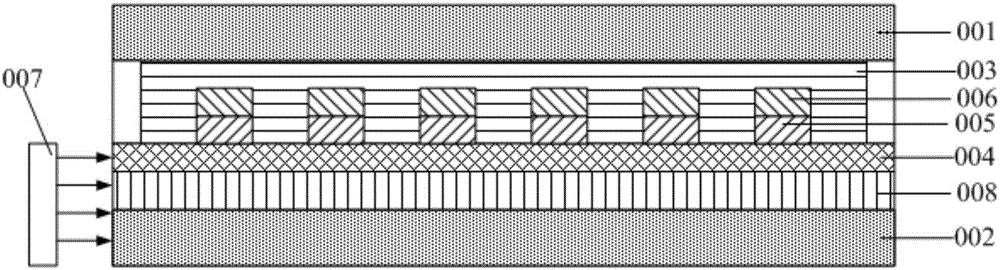
[0087] In this display mode, the above-mentioned display device provided by the embodiment of the present invention, such as Figure 4a As shown, it also includes: an alignment layer 010 (generally PI with a thickness of 30nm-80nm) disposed on the surface of the upper substrate 001 facing the liquid crystal layer 003 and / or disposed on the surface of the electrode structure 006 facing the liquid crystal layer 003, Figure 4a shows that the alignment layer 010 is only provided on the surface of the upper substrate 001 facing the liquid crystal layer 003 . The initial orientation of the liquid crystal molecules in the liquid crystal layer 003 can be controlled by the alignment layer 010, so that the initial direction of the liquid crystal molecules in the liquid crystal layer 003 is perpendicular to the upper substrate 001 and the lo...

example 2

[0094] Example 2: A display mode in which the optical axes of the liquid crystal molecules are rotated in a plane parallel to the display surface.

[0095] In this display mode, the above-mentioned display device provided by the embodiment of the present invention, such as Figure 5a As shown, it also includes: an alignment layer 010 (generally PI with a thickness of 30nm-80nm) disposed on the surface of the upper substrate 001 facing the liquid crystal layer 003 and / or disposed on the surface of the electrode structure 006 facing the liquid crystal layer 003, Figure 5a shows the situation that the alignment layer 010 is only arranged on the surface of the upper substrate 001 facing the liquid crystal layer 003; polarized light. The initial orientation of the liquid crystal molecules in the liquid crystal layer 003 can be controlled by the alignment layer 010 provided, so that the initial orientation of the liquid crystal molecules in the liquid crystal layer 003 is parallel...

example 3

[0099] Example 3: Display mode using blue phase liquid crystal.

[0100] In this display mode, the above-mentioned display device provided by the embodiment of the present invention, such as Figure 6a As shown, the liquid crystal molecules in the liquid crystal layer 003 are selected as the blue phase liquid crystal material, and no alignment film is provided. When no voltage is applied to each electrode structure 600, such as Figure 6a As shown, the liquid crystal molecules are in an isotropic state, such as Figure 6b As shown, it is in an anisotropic state when a voltage is applied, and both polarized lights can be felt in this anisotropic state, so compared with the previous several embodiments, it has a higher light extraction efficiency.

[0101]Specifically, since the blue-phase liquid crystal is isotropic in the non-powered state, the refractive index is the same in all directions, and the refractive index of the two kinds of polarized light passing through the liq...


PUM

PropertyMeasurementUnit
Thicknessaaaaaaaaaa
Thicknessaaaaaaaaaa
Thicknessaaaaaaaaaa

Abstract

The invention discloses a display panel and a display device. The display panel is characterized in that bright dipping direction and color can be selected through coupling of special modes in a waveguide layer by grating coupling structures; reflective index of a liquid crystal layer can be regulated after voltage exerted on the liquid crystal layer is regulated through an electrode structure by setting the refractive index to be (no, ne) through the grating coupling structures, and display gray level is controlled. Due to the selection action of the grating coupling structures on the bright dipping direction, near-to-eye display capable of being monocular focus can be favorably realized. Light rays can be effectively coupled out from the waveguide layer through the grating couple structures for a few grating periods which are generally short, so that the pixel size can be quite small and high definition display is favorably displayed. Due to selection action of the grating coupling structures on the bright dipping color, color films can be omitted, and all parts can be formed by transparent materials so as to achieve highly-transparent transparency display and virtual/augmented reality display.

Description

technical field [0001] The present invention relates to the field of display technology, in particular to a display panel and a display device. Background technique [0002] At present, the existing virtual / augmented reality display and transparent display are all realized by using traditional liquid crystal display panels (LCD) and organic electroluminescent display panels (OLED), which cannot achieve high transparency of the display panel, thus affecting The transmittance of light behind the panel and the transmitted spectrum. [0003] Moreover, as the requirement for display resolution is getting higher and higher, the demand for high-resolution (PPI) display devices is also increasing. However, display devices with high PPI are limited by the manufacturing process and are difficult to develop. [0004] Moreover, the outgoing light of the liquid crystal display panel (LCD) and the organic electroluminescence display panel (OLED) of the traditional structure is generally...

Claims


Application Information

Patent Timeline
IPC IPC(8): G02B27/01G02F1/1335
CPCG02B27/0101G02F1/133504G02B6/005G02B6/0065G02F2201/302G02F1/133615G02F1/133528G02F1/1337G02F1/1343G02F1/133562G02F1/133746G02F1/133749
Inventor 王维杨亚锋陈小川马新利
Owner BOE TECH GRP CO LTD
Why Eureka
Try Eureka