
Laminating machine multi-roll synchronization control device

A technology of synchronous control and synchronous controller, applied in the direction of program control, electrical program control, general control system, etc., can solve the problems of instability, easily damaged motor or heat roller, low synchronization rate, etc., and achieve stability and work efficiency Improve and ensure the synchronization of hot rollers and improve the effect of yield

Inactive Publication Date: 2017-01-04
瑞安市立信印刷机械有限公司
View PDF6 Cites 6 Cited by
  • Summary
  • Abstract
  • Description
  • Claims
  • Application Information

AI Technical Summary

Problems solved by technology

Most of the traditional laminating machines are single-roller, and the laminating machine with this structure has low efficiency, poor stability and low yield
In order to overcome this defect, a double-roller or multi-roller laminating machine has appeared on the market. The laminating machine with this structure drives two or more hot rollers to rotate at the same time through a motor, or separately through multiple motors. Drive the heat roller to rotate; the first transmission method requires a large power of the motor, and the energy consumption in the production process is also relatively large, and it is unstable, and it is easy to damage the motor or the heat roller; the second transmission method has a low synchronization rate , it is also difficult to operate

Method used


Image

  • Laminating machine multi-roll synchronization control device

Examples


Embodiment 1

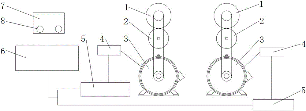
[0021] Such as figure 1 The multi-roller synchronous control device of the laminating machine shown includes two hot rollers 1 and a pressure roller 2 corresponding to the hot rollers 1. The hot rollers 1 are connected with servo motors, and the hot rollers 1 and the servo The motors are connected by chains, the servo motors are provided with encoders 4, and the encoders 4 are connected with servo controllers, and the servo controllers are connected with the PLC control system 6, and the PLC control system 6 is equipped with There is a control panel 7, and the control panel 7 is a touch screen, and the touch screen is provided with a fine-tuning device 8 that can adjust the servo motors respectively.

[0022] The servo motor is used to drive the heat roller 1 corresponding to it to rotate; the encoder 4 is used to read the rotation signal of the servo motor corresponding to it and feed it back to the servo controller, and then adjust it through the servo controller. The signa...

Embodiment 2

[0024] Such as figure 1 The multi-roller synchronous control device of the laminating machine shown includes two hot rollers 1 and a pressure roller 2 corresponding to the hot rollers. The hot rollers 1 are connected with ordinary motors, and the hot rollers 1 and ordinary motors Connected by a chain, the ordinary motor is provided with an encoder 4, and the encoder 4 is connected with a synchronous controller, and the synchronous controller is provided with a synchronous card and a frequency converter, and the synchronous controller is controlled with a PLC. The system 6 is connected, and the PLC control system 6 is provided with a control panel 7, and the control panel 7 is a touch screen, and the touch screen is provided with a fine-tuning device 8 that can adjust ordinary motors respectively.

[0025] The ordinary motor is used to drive the corresponding heat roller to rotate; the encoder 4 is used to read the rotation signal of the ordinary motor corresponding to it and f...


PUM


Abstract

A laminating machine multi-roll synchronization control device comprises a plurality of heat rollers and pressure rollers arranged corresponding to the heat rollers. The heat rollers are connected with motors, the motors are provided with encoders, the encoders are connected with controllers, the controllers are connected with a PLC control system, and the PLC control system is provided with a control panel. The laminating machine multi-roll synchronization control device is simple in structure, reasonable, stable in work and high in efficiency and can effectively ensure the synchronization of the heat rollers.

Description

technical field [0001] The invention relates to a synchronous control device, in particular to a multi-roller synchronous control device for a laminating machine. Background technique [0002] The laminating machine can be divided into two categories: instant coating laminating machine and pre-coating laminating machine. It is a special equipment for paper, board and film lamination. It is pressed together by a rubber roller and a heating roller to form a paper-plastic product. Most of the traditional laminating machines are single-roller, and the laminating machine with this structure has low efficiency, poor stability and low yield. In order to overcome this defect, a double-roller or multi-roller laminating machine has appeared on the market. The laminating machine with this structure drives two or more hot rollers to rotate at the same time through a motor, or separately through multiple motors. Drive the heat roller to rotate; the first transmission method requires a ...

Claims


Application Information

Patent Timeline
Patent Type & Authority Applications(China)
IPC IPC(8): G05B19/05
CPCG05B19/058
Inventor 池小钦
Owner 瑞安市立信印刷机械有限公司
Learn More