Quantum dot light-emitting component, backlight module and display device

A technology of quantum dot luminescence and quantum dot layer, which is applied in the direction of electrical components, lighting devices, fixed lighting devices, etc., can solve the problems of less light to excite the quantum dot layer and low LED luminous efficiency, so as to reduce absorption loss and improve light output efficiency effect

Active Publication Date: 2017-01-04
HISENSE VISUAL TECH CO LTD
View PDF3 Cites 12 Cited by
  • Summary
  • Abstract
  • Description
  • Claims
  • Application Information

AI Technical Summary

Problems solved by technology

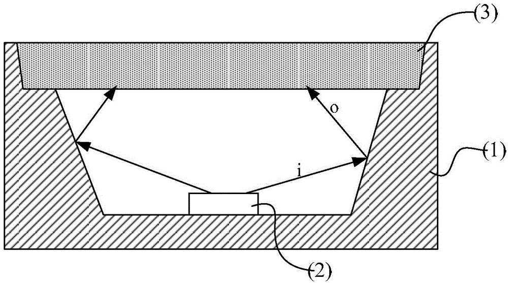
[0003] Currently, the backlight solution that can achieve the highest color gamut in the industry is the solution that blue light excites quantum dot materials to produce white light, and the color gamut can reach 100% NTSC or more. However, if figure 1 A quantum dot LED is shown, comprising a support frame (1), an LED chip (2) arranged at the bottom of the support frame (1), and a quantum dot layer (3) arranged at the top opening of the support frame (1), wherein The large-angle light i emitted from the LED chip (2) is irradiated on the side wall of the support frame (2) and the reflected light o is used to excite the quantum dot layer to generate white light, and the large-angle light i is irradiated on the support frame ( 2) Partially absorbed on the side wall, so that the light that actually excites the quantum dot layer is relatively small, which ultimately leads to the low luminous efficiency of the LED made of quantum dots

Method used


Image

  • Quantum dot light-emitting component, backlight module and display device
  • Quantum dot light-emitting component, backlight module and display device
  • Quantum dot light-emitting component, backlight module and display device

Examples


Embodiment Construction

[0040] The following will clearly and completely describe the technical solutions in the embodiments of the present invention with reference to the accompanying drawings in the embodiments of the present invention. Obviously, the described embodiments are only some, not all, embodiments of the present invention. Based on the embodiments of the present invention, all other embodiments obtained by persons of ordinary skill in the art without making creative efforts belong to the protection scope of the present invention.

[0041] In describing the present invention, it is to be understood that the terms "center", "upper", "lower", "front", "rear", "left", "right", "vertical", "horizontal", The orientations or positional relationships indicated by "top", "bottom", "inner", "outer", etc. are based on the orientations or positional relationships shown in the drawings, and are only for the convenience of describing the present invention and simplifying the description, rather than in...


PUM


Abstract

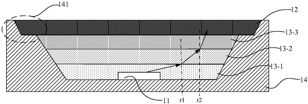
An embodiment of the invention provides a quantum dot light-emitting component, a backlight module and a display device, relates to the field of photoelectric devices, and can reduce back scattering light loss and improve light-emitting efficiency of the quantum dot light-emitting component. The quantum dot light-emitting component comprises a support frame, an excitation light source, a refraction layer and a quantum dot layer, wherein the support frame is in a groove shape; the excitation light source is arranged at the bottom of a groove in the support frame, and is used for emitting excitation light; the refraction layer is arranged in the light output direction of the excitation light source, and the refraction layer is made of a light transmitting material; the propagation direction of the excitation light emitted by the excitation light source deflects to the center normal direction of a light output plane of the excitation light source after the excitation light passes through the refraction layer; the quantum dot layer is arranged on the refraction layer, and the quantum dot layer emits light when excited by the excitation light; and the excitation light source, the refraction layer and the quantum dot layer as well as the support frame are packaged together to form an integrated enclosed structure. The embodiment of the invention is used for manufacturing the quantum dot light-emitting component.

Description

technical field [0001] The invention relates to the field of optoelectronic devices, in particular to a quantum dot light-emitting element, a backlight module and a display device. Background technique [0002] Currently the most common LCD TVs on the market, the color gamuts they can display are generally not large, and their display color gamuts are generally 68% to 72% NTSC (English full name: National Television Standards Committee, Chinese abbreviation: National Television Standards Committee) standard Left and right, so it can't provide good color effect. With the improvement of consumers' requirements for image quality, high color gamut backlight technology is becoming the focus of research in the industry. The color gamut of ULED (Ultra Light Emitting Diode, extreme light-emitting diode) products can reach more than 85% NTSC, with outstanding color expression and good market response. A higher color gamut is the development direction of the next generation of ULED p...

Claims


Application Information

Patent Timeline
Patent Type & Authority Applications(China)
IPC IPC(8): H01L33/48F21S8/00H01L33/58G02F1/13357
CPCF21S8/00G02F1/1336H01L33/48H01L33/483H01L33/58H01L2933/005H01L2933/0058
Inventor 李富琳曹建伟刘卫东黄顺明
Owner HISENSE VISUAL TECH CO LTD
Why Eureka
Try Eureka