Gas cooling device and gas cooling method of power battery pack

A power battery pack and gas cooling technology, which is applied in the fields of high-power power battery pack gas cooling for vehicles, high-power power battery pack gas cooling devices for vehicles, and power battery pack gas cooling devices, can solve the problem of consuming power battery power and water cooling. The problems of large system volume and large cooling system volume can achieve the effect of simple structure, good cooling effect and increased volume

Inactive Publication Date: 2017-01-04
肖克建
View PDF5 Cites 7 Cited by
  • Summary
  • Abstract
  • Description
  • Claims
  • Application Information

AI Technical Summary

Problems solved by technology

Water cooling generally requires cooling water tanks, circulating water pipes, radiators, sealing devices, electric water pumps and other devices. The main disadvantages of water cooling are: the water cooling system itself is large in size and consumes power from the power battery
Air cooling generally requires radiators and electric fans. The main disadvantages of this type of air cooling are: like water cooling, the cooling system itself is larger in size and consumes power from the power battery; there is another type of air cooling that relies on the power of the car The cold air poured in from the outside during the driving process is used to convectively cool the power battery pack. The main defect of this type of air cooling is that the cooling process is limited by the outside air temperature, wind speed and other conditions, and it cannot be cooled when parking or charging.
Both the method and the device need to consume a large amount of liquid nitrogen

Method used


Image

  • Gas cooling device and gas cooling method of power battery pack
  • Gas cooling device and gas cooling method of power battery pack
  • Gas cooling device and gas cooling method of power battery pack

Examples


Embodiment 1

[0045] Such as Figure 4-10 As shown, the power battery pack gas cooling device includes:

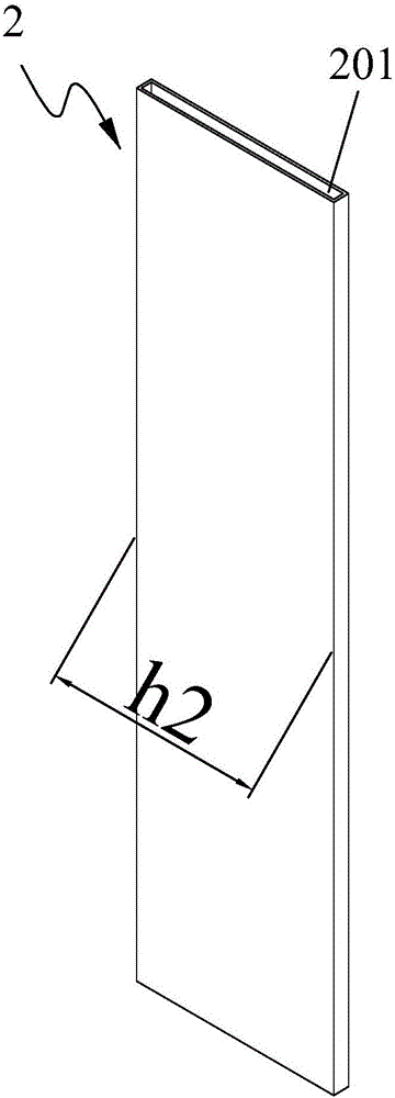
[0046] - Disc cooling medium channel 2, such as Figure 2-5 As shown in , 10, the disc-type cooling medium channel is used for gas coolant flow, and the disc-type cooling medium channel is located in the middle of the two rows of power battery cells 4; the cooling medium is preferably air or nitrogen;

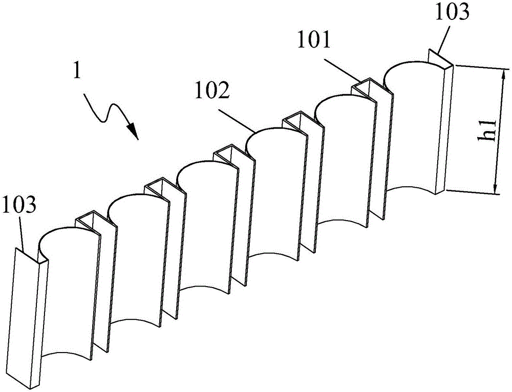
[0047] --Such as figure 1 , 4As shown in -10, at least one pair of heat sinks 1, any one of the heat sinks includes at least one arc portion 102; the inner side of the combined pair of heat sink arc portions matches the shape of the battery core of the power battery pack, and the combined The outer sides of the arc portion of the last pair of fins are tangent to the wall of the disk-type cooling medium channel; and the combined pair of fin ends 103 are in contact with the disk-type cooling medium channel.

[0048] For example, if Figure 4 As shown, a battery pack has 8 columns x 6 ...

Embodiment 2

[0055] like figure 1 , 4 , 5, and 10, as an improvement of the power battery pack gas cooling device of the present invention, any one of the cooling fins includes at least two arc-shaped parts 102, and a raised part is arranged in the middle of the two arc-shaped parts 101, such as Figure 9 As shown in , the raised portion is in contact with the disk cooling medium channel. The protruding part 101 can function as a thermal bridge, speed up heat transfer, and improve heat dissipation and cooling effects.

[0056] like Figure 4 As shown, a battery pack has 8 columns x 6 rows of battery cells. like figure 1 , 5 , 10, a heat sink 1 has six arcs 102, five protrusions 101 and two ends 103. like Figure 4 As shown, a pair of heat sinks can wrap a row of battery cells.

[0057] The heat of the heat sink can be transferred to the plate-type cooling medium channel through more reliable contact parts, further improving the cooling effect.

Embodiment 3

[0059] like Figure 1-10 As shown, the power battery pack gas cooling method, wherein:

[0060] There is a disc-type cooling medium channel 2 between the cells of the two rows of power battery packs, and the disc-type cooling medium channel is used for gas coolant flow; the cooling medium is preferably air or nitrogen;

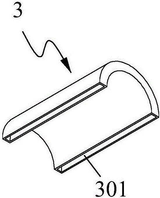
[0061] The outside of any battery core in the power battery pack is covered with an arc-shaped heat sink 1, and the heat of the battery core passes through the arc portion 102 of the heat sink and the end portion 103 of the heat sink and the heat in the disk cooling medium passage. The gas realizes heat exchange.

[0062] When working, the gas cooling medium, such as air, nitrogen, passes through the plate cooling medium channel. The heat sink transfers heat to the plate-type cooling medium channel through the arc and both ends, and the flowing gas coolant takes out the heat conducted by the heat sink to the plate-type cooling medium channel to achieve effic...


PUM


Abstract

The invention relates to a gas cooling device of a power battery bank. In the technical scheme, the gas cooling device of the power battery pack comprises a disc type cooling medium channel (2) and at least one pair of cooling fins (1), wherein the disc type cooling medium channel is used for a gas coolant to flow and is located between two rows of battery cells (4) of the power battery pack, any one of the cooling fins comprises at least one arc-shaped part (102), inner sides of the arc-shaped parts of the pair of cooling fins after combination are matched with the appearance of the battery cells of the power battery pack, outer sides of the arc-shaped parts of the pair of cooling fins after combination are tangential to a wall of the disc type cooling medium channel, and end parts (103) of the pair of cooling fins after combination are in contact with the disc type cooling medium channel. After adoption of the technical scheme, the cooling effect of the battery pack is improved.

Description

technical field [0001] The first invention relates to a gas cooling device for a power battery pack, in particular to a gas cooling device for a high-power power battery pack used in a vehicle. The invention belongs to the technical field of environmental protection and energy-saving cooling process equipment and the like. Its main function: to reduce the temperature of the power battery pack in a timely and efficient manner through the flowing gas. [0002] The second invention relates to a gas cooling method for a power battery pack, in particular to a gas cooling method for a high-power power battery pack used in a vehicle. The invention belongs to the technical field of environmental protection and energy-saving cooling process equipment and the like. Its main function: use the flowing gas to reduce the temperature of the power battery pack in a timely and efficient manner. . [0003] Invention 1 and Invention 2 both relate to gas cooling the power battery pack, Invent...

Claims


Application Information

Patent Timeline
Patent Type & Authority Applications(China)
IPC IPC(8): H01M10/655H01M10/6561H01M10/625H01M10/613
CPCH01M2220/20Y02E60/10
Inventor 肖克建祁威吴锁华
Owner 肖克建
Why Eureka
Try Eureka