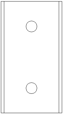
Connection device for insulating tubular busbar ends

A connecting device and insulating tube technology, which is applied in the direction of connection, connection insulation, conductive connection, etc., can solve the problems of uneven surface, large welding joint resistance, uneven electric field, etc., and achieve uniform electric field distribution, high insulation level, and convenient The effect of air circulation

Active Publication Date: 2018-10-30
山东泰开电缆科技有限公司
View PDF3 Cites 0 Cited by
  • Summary
  • Abstract
  • Description
  • Claims
  • Application Information

AI Technical Summary

Problems solved by technology

[0003] One is the flattening method of the end of the tubular busbar. The tubular conductor is flattened into a flat shape, and then connected to other busbars with lap plates and bolts. Due to the flattening method, the flat surface is often uneven and the sides of the flat plate are cracked. And other phenomena, resulting in insufficient effective lapping surface, unable to meet the demand of carrying capacity, resulting in heat generation at the joint and large partial discharge;
[0004] The second is the built-in connection method. Insert the connecting tube with the same outer diameter as the inner diameter of the insulating tubular busbar into both ends of the busbar, and the end of the busbar is axially slit, so as to connect and transmit current. This connection method is due to the opening of the busbar end. Seams, if there is vibration, the overlapping surface becomes smaller or virtual connection phenomenon, resulting in poor contact and high temperature rise;
[0005] The third is the external connection method. The connecting pipe is composed of two symmetrical semicircles, with connecting ears and threaded holes. The inner diameter is consistent with the outer diameter of the insulating tubular busbar. The two busbars are connected by connecting pipes and bolts. Connecting by means of connection, because the connecting ear protrudes from the busbar, it will lead to uneven electric field, which will easily cause the stress concentration of the electric field here and cause breakdown, which cannot meet the connection performance of the insulating tubular busbar end;
[0006] The fourth is the welding type. This method has high technical requirements for welding workers, complicated installation, high resistance of the welding joint, and the welding joint is easy to break;
[0007] Fifth, the conductor at the end of the insulating tubular busbar is flattened into a flat surface, and is connected with the flat surface of other tubular busbars with lap plates and bolts. Insufficient joints, unable to meet the requirements of current carrying capacity, resulting in problems such as heat generation at the joints and large partial discharges;
[0008] The sixth is the hoop connection. The hoop is composed of two symmetrical semicircles with connecting ears and threaded holes. It is connected by bolt clamping and fixing. Since the connecting ears protrude out of the busbar, the electric field will be uneven, which is easy to cause here Breakdown occurs due to the concentration of electric field stress

Method used


Image

  • Connection device for insulating tubular busbar ends
  • Connection device for insulating tubular busbar ends
  • Connection device for insulating tubular busbar ends

Examples


Embodiment Construction

[0048] According to the review guidelines, terms such as "having", "comprising" and "including" used in the present invention should be understood as not deriving the presence or addition of one or more other elements or combinations thereof.

[0049] In the description of the present invention, it should be noted that the terms "center", "upper", "lower", "left", "right", "vertical", "horizontal", "inner", "outer" etc. The indicated orientation or positional relationship is a generally expressed orientation or positional relationship, which is only for the convenience of describing the present invention and simplifying the description, rather than indicating or implying that the referred device or element must have a specific orientation, be constructed and operated in a specific orientation , and therefore cannot be construed as a limitation of the present invention. In addition, the terms "first", "second", and "third" are used for descriptive purposes only, and should not ...


PUM


Abstract

The invention provides a connection device applied to insulation tube type busbar ends. The device comprises a ferrule (1) which is arranged between the insulation tube type busbar ends and is used for satisfying the electrical property of the joint of the insulation tube type busbar ends, a pressing plate device which is arranged between the insulation tube type busbar ends and hoops two insulation tube type busbar ends in a plane-to-plane contact manner, or a tube-expansion device which elastically hoops two insulation tube type busbar ends. Through the ferrule (1), insulation and electric shielding of the joint of the insulation tube type busbar ends are realized. Through the pressing plate device, plane-to-plane connection of the insulation tube type busbar ends is realized, and the contact area is increased. Through the tube-expansion device, interference connection of the insulation tube type busbar ends is realized, and the relative contact pressure is increased. Crushing, built-in connection and external connection are avoided. The connection performance requirement of the insulation tube type busbar ends is met.

Description

1. Technical field [0001] The invention relates to a connection device, in particular to a connection device used for the end of an insulating tubular busbar. 2. Background technology [0002] In order to meet the needs of large rated current of the low-voltage side incoming line of the transformer with large main variable capacity, the insulating tubular busbar has the characteristics of large carrying capacity, low skin effect, low temperature rise, good insulation performance, good heat dissipation and high mechanical strength. Technical performance, replacing the rectangular busbar and bare busbar, during the installation of the low-voltage side of the transformer, due to the limited length of the insulating tubular busbar, it is necessary to connect two insulating tubular busbars, so it is used for insulating tubular busbar terminals The connection device is an important cable accessory. In an existing connection device for insulating tubular busbar ends, the connection...

Claims


Application Information

Patent Timeline
Patent Type & Authority Patents(China)
IPC IPC(8): H01R11/01H01R11/09H01R11/26H01R4/70
CPCH01R4/70H01R11/01H01R11/09H01R11/26
Inventor 宋增国梁美丽刘浩李涛
Owner 山东泰开电缆科技有限公司
Why Eureka
Try Eureka