HDI circuit board blind hole wiring method
A wiring method and circuit board technology, which is applied in chemical/electrolytic methods to remove conductive materials, printed circuits, printed circuits, etc., can solve the problems of blind vias that cannot be routed, blind vias cannot perform pattern transfer, etc., and achieve signal transmission. Stability, good anti-noise performance, and the effect of improving wiring density
- Summary
- Abstract
- Description
- Claims
- Application Information
AI Technical Summary
Problems solved by technology
Method used
Image

Examples
Embodiment 1
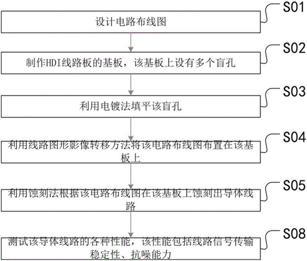
[0025] Embodiment 1, a blind hole wiring method of an HDI circuit board, the HDI circuit board in this embodiment is a single
[0026] Laminates. Its specific wiring method includes the following steps.
[0027] S01: Design circuit wiring diagram. In the specific implementation, first design the circuit wiring diagram passing through the blind hole, design the production plan according to the requirements of the layout circuit wiring diagram, and select the materials used for evaluation and pre-compensate the conductor thickness, width and insulating layer thickness during etching . Since the circuit wiring diagram is set according to product requirements, there is no limitation in this embodiment.
[0028] S02: Making a substrate of an HDI circuit board, and the substrate is provided with a plurality of blind holes. During specific implementation, the position of the blind hole is set according to the requirements of the circuit line. The design requirements of blind hol...
Embodiment 2
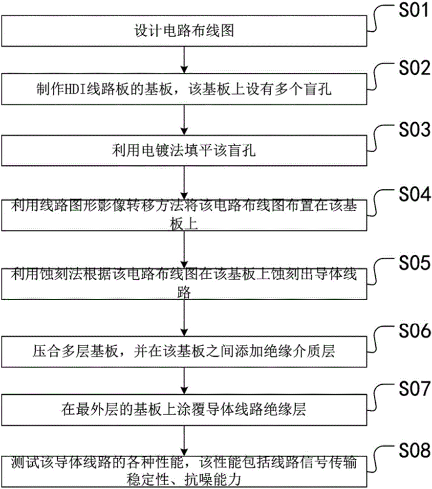
[0037] Embodiment 2. The difference between this embodiment and Embodiment 1 is that the HDI circuit board in this embodiment is a multi-layer circuit board. Therefore, the blind hole wiring method of the HDI circuit board in this embodiment further includes the following steps.
[0038] The following steps are also included after step S05 of Embodiment 1.
[0039] S06: Laminating the multi-layer substrates, and adding an insulating medium layer between the substrates. During specific implementation, the thickness and uniformity of the insulating medium layer are controlled, that is, the thickness and distribution of the insulating medium layer in step S06 are uniform.
[0040] S07: Coating an insulating layer of conductor lines on the outermost substrate.
[0041] Wherein, the step S07 is after the step S06. The thickness and distribution of the insulating layer in the step S07 are uniform.
[0042] During the implementation of the above embodiments, it is mainly investiga...
PUM
 Abstract
Description
Claims
Application Information
 - R&D
- Intellectual Property
- Life Sciences
- Materials
- Tech Scout
- Unparalleled Data Quality
- Higher Quality Content
- 60% Fewer Hallucinations
Browse by: Latest US Patents, China's latest patents, Technical Efficacy Thesaurus, Application Domain, Technology Topic, Popular Technical Reports.
© 2025 PatSnap. All rights reserved.Legal|Privacy policy|Modern Slavery Act Transparency Statement|Sitemap|About US| Contact US: help@patsnap.com