
Auto-mounting tray for scattered or short-taped devices

A component and scattered technology, applied in the field of trays carrying scattered or short-braided electronic components, can solve problems such as the inability to meet the placement requirements of the placement machine, the small amount of components used, and the lack of placement accuracy. Fast and stable picking, easy operation, and improved assembly accuracy

Inactive Publication Date: 2017-01-04
CHANGCHUN INST OF OPTICS FINE MECHANICS & PHYSICS CHINESE ACAD OF SCI
View PDF5 Cites 6 Cited by
  • Summary
  • Abstract
  • Description
  • Claims
  • Application Information

AI Technical Summary

Problems solved by technology

[0004] In order to solve the problem of time-consuming and labor-intensive re-taping after the completion of the screening of existing electronic components, high production costs, and the small amount of some components used, the length after braiding is too short to meet the placement requirements of the placement machine. Manual placement causes problems such as insufficient placement accuracy, and provides an automatic placement tray for scattered or short taped components

Method used


Image

  • Auto-mounting tray for scattered or short-taped devices
  • Auto-mounting tray for scattered or short-taped devices
  • Auto-mounting tray for scattered or short-taped devices

Examples


specific Embodiment approach 1

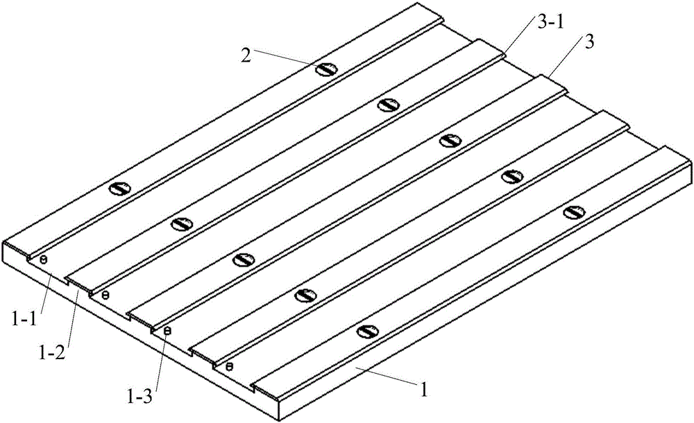
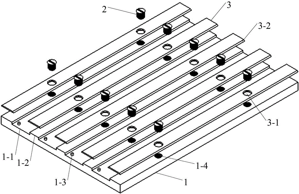
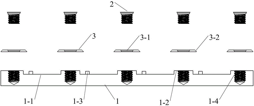
[0015] Specific implementation mode one, combination Figure 1 to Figure 5 To illustrate this embodiment, an automatic mounting tray for scattered or short braided components includes a bottom table 1, a fastening screw 2 and an upper pressure plate 3;

[0016] The bottom platform 1 is an equidistant array structure of grooves, and includes three parts: a carrier tape inlay groove 1-1, a boss 1-2, and a carrier tape positioning pin 1-3. The stages 1-2 are arranged at equal intervals, the carrier tape inlay grooves 1-1 are used to place the component carrier tape, the carrier tape positioning pins 1-3 are used to complete the precise positioning of the component carrier tape, the boss 1-2 The upper surface is designed with two positioning holes 1-4 with dual functions of size positioning and mechanical fixing;

[0017] The fastening screw 2 is a slotted countersunk head screw. After fastening, the fastening screw 2 needs to be completely sunk into the countersunk locating hole 3-1 ...

specific Embodiment approach 2

[0022] Specific embodiment two, this embodiment is an example of using a scattered or short braided component automatic placement tray described in specific embodiment one to position and fix short braided components:

[0023] Put the short braid into the carrier tape inlay slot 1-1, and at the same time insert the positioning pins 1-3 into the positioning hole of the carrier tape, place the upper plate 3 on the surface of the boss 1-2, and ensure the sinking of the upper plate 3 The head positioning hole 3-1 is accurately aligned with the positioning hole 1-4 on the boss 1-2. At the same time, the upper pressure plate 3 will further press the carrier tape straight into the carrier tape mounting groove 1-1, and tighten the screws 2 Screw the countersunk positioning hole 3-1 into the positioning hole 1-4, keep the fastening screw 2 lower than the upper surface of the upper plate 3, and finally peel off the heat-sealed cover tape on the surface of the short braid. Through the above...

specific Embodiment approach 3

[0024] Specific embodiment three. This embodiment is an example of using an automatic placement tray for scattered or short braided components described in the first embodiment to locate and fix scattered components:

[0025] First determine the type of carrier tape (reusable twice) that is suitable for the scattered components, and complete the unloaded tape fixing process according to the above-mentioned short tape component fixing process, and finally put the scattered components on the carrier tape one by one for use Place the electronic components in the holes to complete the precise fixation of the scattered components.


PUM


Abstract

An auto-mounting tray for scattered or short-taped devices relates to the field of electronic assembly and solves the problems that re-taping for existing electronic device screening is time-consuming and labor-consuming with high production cost, post-taping length is too small due to part of the devices using little taping such that mounting requirements of a surface-mounting machine cannot be met, and manual mounting leads to poor mounting precision; the auto-mounting tray comprises a bottom table and an upper press plate, the bottom table is of equally-spaced groove array structure and comprises tape receiving grooves, terraces and tape positioning pins, the tape receiving grooves are used for holding device tapes, the tape positioning pins are used for positioning the device tapes, and the upper press plate is fixed to positioning holes of the terraces through fastening screws so as to fix the device tapes. The bottom table and the upper press plate enable device tapes to be reused, the scattered devices are arrayed, quick and stable pickup of suction nozzles is guaranteed, auxiliary cost is reduced, and assembly accuracy is improved; the auto-mounting tray is simple in structure, easy to operate and convenient for an operator to use.

Description

Technical field [0001] The invention relates to the field of electronic assembly, in particular to a tray used for carrying scattered or short braided electronic components in the automatic placement process of a placement machine. Background technique [0002] With the rapid development of electronic technology, printed circuit board (PCB) automatic surface assembly technology (SMT) has been widely popularized and developed in military research institutes such as aerospace, aviation, and electronic systems. However, the multi-variety and small-batch production mode of military institutes restricts the performance of the placement machine to a certain extent, and the components of military electronic products need to be screened before assembly. The screening process is bound to cause components The destruction of the original braid made the components unable to be mounted using the placement machine, which greatly affected the assembly efficiency of the PCB. Currently, componen...

Claims


Application Information

Patent Timeline
Patent Type & Authority Applications(China)
IPC IPC(8): H05K13/02
CPCH05K13/02
Inventor 张艳鹏石宝松王玉龙
Owner CHANGCHUN INST OF OPTICS FINE MECHANICS & PHYSICS CHINESE ACAD OF SCI
Learn More