Punching device for fuselage frame

A punching device, aircraft fuselage technology, applied in feeding devices, aircraft parts, transportation and packaging, etc., can solve problems such as quality cannot be guaranteed, and achieve the effect of improving punching efficiency, stable high-quality connection, and manufacturing precision control.

Inactive Publication Date: 2017-01-11
CHENGDU AIRCRAFT INDUSTRY GROUP
View PDF9 Cites 5 Cited by
  • Summary
  • Abstract
  • Description
  • Claims
  • Application Information

AI Technical Summary

Problems solved by technology

[0003] In order to overcome the defect that the quality cannot be guaranteed when the manual assembly operation is used in the production of small aircraft in China, the invention provides a punching device for the frame of the aircraft fuselage. Automatic drilling of parts with curved surface and poor opening, which improves product quality and work efficiency, and reduces labor intensity of workers

Method used


Image

  • Punching device for fuselage frame
  • Punching device for fuselage frame
  • Punching device for fuselage frame

Examples


Embodiment 1

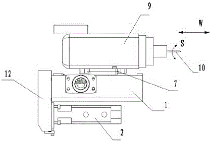
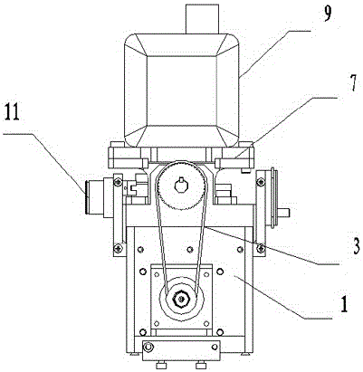
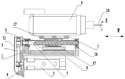
[0020] This embodiment provides an aircraft fuselage frame punching device, and the function of the punching device is to replace manual punching of the aircraft fuselage frame. The device needs to be installed on a three-coordinate machine tool, such as Figure 6 As shown, the three coordinates of the three-coordinate machine tool are three coordinates of x, y, and z. This embodiment is connected to the AC double swing head of the three-coordinate machine tool. AC refers to the two directions of the swing of the double swing head. A direction and C direction, in this embodiment, when punching holes, it performs linear feeding along the W direction in the figure to complete the punching action. Such as Figure 1-Figure 4 As shown, the specific structure of this embodiment is as follows: including a drill bit 10, an electric spindle 9, a mounting plate assembly 1, a connecting seat 7, a support assembly and a drive assembly, the support assembly includes a support guide rail 8...

Embodiment 2

[0023] This embodiment provides an aircraft fuselage frame punching device, and the function of the punching device is to replace manual punching of the aircraft fuselage frame. The device needs to be installed on a three-coordinate machine tool, such as Figure 6 As shown, the three coordinates of the three-coordinate machine tool are three coordinates of x, y, and z. This embodiment is connected to the AC double swing head of the three-coordinate machine tool. AC refers to the two directions of the swing of the double swing head. A direction and C direction, in this embodiment, when punching holes, it performs linear feeding along the W direction in the figure to complete the punching action. Such as Figure 1-Figure 4As shown, the specific structure of this embodiment is as follows: including a drill bit 10, an electric spindle 9, a mounting plate assembly 1, a connecting seat 7, a support assembly and a drive assembly, the support assembly includes a support guide rail 8 ...


PUM


Abstract

The invention discloses a punching device for a fuselage frame. The punching device comprises a drill bit, an electric spindle, an installation plate assembly, a connection base, a supporting assembly and a drive assembly. The drill bit is installed on the electric spindle. The electric spindle is installed on the connection base. The connection base is installed on the supporting assembly. The drive assembly drives the connection base to slide on the installation plate assembly. The supporting assembly and the drive assembly are both installed on the installation plate assembly. By means of the punching device, automatic punching is conducted on large-curvature, double-curved-surface and poor-openness parts of small fuselage frames, the product quality and the work efficiency are improved, and the labor intensity of workers is lowered.

Description

technical field [0001] The invention belongs to the aircraft manufacturing industry, and in particular relates to a device for drilling holes on an aircraft fuselage frame. Background technique [0002] According to statistics, 70% of aircraft body fatigue failure accidents are caused by the structural connection parts, and 80% of the fatigue cracks occur in the connection holes. It can be seen that the connection quality greatly affects the life of the aircraft. In terms of precision hole making abroad, many advanced drilling tools have been developed, and automatic hole making tools and equipment are used to make holes, such as automatic feed drills, automatic drilling and riveting machines, robots, laser-guided drilling machines, and precision machining centers. The holes ensure the precision of the hole making and realize the smooth hole making. In recent years, some automatic drilling and riveting machines have also been introduced in China, which are mainly used for t...

Claims


Application Information

Patent Timeline
Patent Type & Authority Applications(China)
IPC IPC(8): B23B41/00B23Q5/40B23Q5/48
CPCB23B41/00B23B2215/04B23Q5/402B23Q5/48
Inventor 熊红
Owner CHENGDU AIRCRAFT INDUSTRY GROUP
Why Eureka
Try Eureka