Online optimal shearing method for defective steel plates
A defect and steel plate technology, applied in the field of thick plate shearing production control, can solve problems such as ineffective treatment, reduced steel plate yield, and large waste plates, so as to reduce the cost of feeding materials and increase the yield
- Summary
- Abstract
- Description
- Claims
- Application Information
AI Technical Summary
Problems solved by technology
Method used
Image
Examples
Embodiment 1
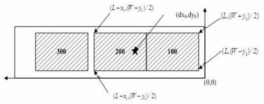
[0076] Embodiment 1, the motherboard is a sequential A-type assembly motherboard:
[0077] like Figure 8 As shown, the rolled large slab is composed of 3 sub-slabs from 100 to 300. By dividing the mother board area, 100 and 200 belong to one mother board, and 300 belongs to one mother board. It is found that the defect position is located in the 100 and 200 mother boards , query the two sub-boards in the motherboard again, find that the defect is located in the sub-board of 200, and then avoid the defect by translating the 200 sub-board, and re-divide the motherboard area. At this time, the motherboard composed of 100 and 200 is in A rough cutting point is added at the cutting head, and the tail of the 100 sub-board includes a cut-to-length cut at the cut-to-length shear, which is used to separate the defective part.
Embodiment 2
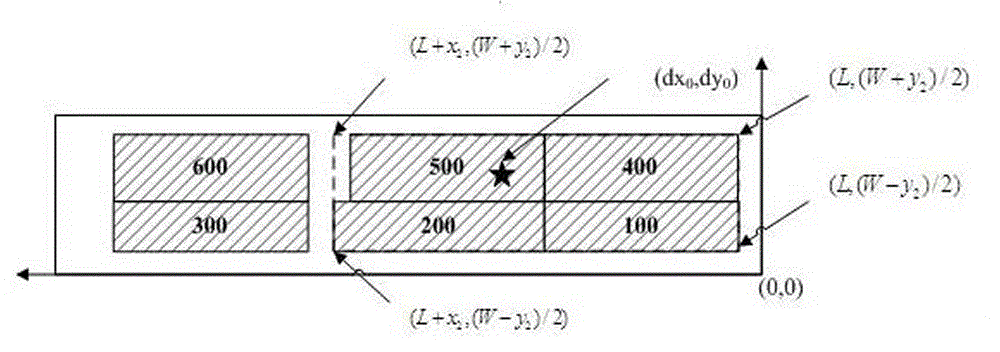
[0078] Embodiment 2, the motherboard is a split-type S-type assembly motherboard
[0079] like Figure 9 As shown, the large rolling plate is composed of 6 sub-plates from 100 to 600. By dividing the mother plate area, 100, 200, 400 and 500 belong to one mother plate, and 300 and 600 belong to one mother plate. By querying the motherboard area and defect location, it is determined that the defect is located in the motherboard of 100, 200, 400, and 500, and the four daughter boards of 100, 200, 400, and 500 in the defective motherboard are checked again, and 500 is determined to be a defective daughter board. The defect was avoided by moving the 500 sub-board, and the motherboard area was re-divided. At this time, the cutting head shears only translate the rough cutting point, and the head of the 500 sub-board adds a knife and a fixed length to the cut-to-length scissors to separate defects. part.
Embodiment 3
[0080] Embodiment 3, the motherboard is a torch-cut type G-type assembly motherboard
[0081] like Figure 10 As shown, the rolled large slab is composed of 7 sub-slabs from 100 to 700. By dividing the mother board area, 100 to 300 belong to one mother board, 400 to 500 belong to one mother board, and 600 and 700 belong to one mother board. By querying the motherboard area and defect location, it is determined that the defect is located in the motherboard of 100 to 300, and the three sub-boards of 100 to 300 in the defective motherboard are checked again, and 200 is determined to be the defective sub-board. Avoidance is carried out, and the mother board area is re-divided. At this time, the cutting head shears only translate the rough cutting point.
[0082] The optimized shearing method of the present invention effectively avoids defective parts, ensures that all the sub-plates can be successfully sheared, and reduces the cost of feeding materials. For the situation where t...
PUM
 Abstract
Description
Claims
Application Information
 - R&D
- Intellectual Property
- Life Sciences
- Materials
- Tech Scout
- Unparalleled Data Quality
- Higher Quality Content
- 60% Fewer Hallucinations
Browse by: Latest US Patents, China's latest patents, Technical Efficacy Thesaurus, Application Domain, Technology Topic, Popular Technical Reports.
© 2025 PatSnap. All rights reserved.Legal|Privacy policy|Modern Slavery Act Transparency Statement|Sitemap|About US| Contact US: help@patsnap.com


