Novel method for representing ultra-precision cutting surface grain-boundary relief

A cutting surface, ultra-precision technology, applied in the field of characterization of super-precision cutting surface grain boundary embossment, can solve the problem of being unable to distinguish the difference, and achieve the effect of reducing signal interference

Inactive Publication Date: 2017-01-11
MATERIAL INST OF CHINA ACADEMY OF ENG PHYSICS
View PDF5 Cites 3 Cited by
  • Summary
  • Abstract
  • Description
  • Claims
  • Application Information

AI Technical Summary

Problems solved by technology

[0005] In view of the above problems, the present invention discloses a new method capable of effectively characterizing grain boundary relief of ultra-precision cutting surfaces, which can effectively identify grain boundary relief characteristics, quantitatively reflect the morphology feature information of ultra-finishing surface at the microscopic scale, and solve the problem of Solve the problem that when the ultra-precision cutting surface has machining tool marks and grain boundary relief information at the same time, the traditional roughness measurement cannot distinguish the difference

Method used


Image

  • Novel method for representing ultra-precision cutting surface grain-boundary relief
  • Novel method for representing ultra-precision cutting surface grain-boundary relief
  • Novel method for representing ultra-precision cutting surface grain-boundary relief

Examples


Embodiment Construction

[0030] It should be noted that, in the case of no conflict, the embodiments of the present invention and the features in the embodiments can be combined with each other.

[0031] The present invention will be described in detail below with reference to the accompanying drawings and examples.

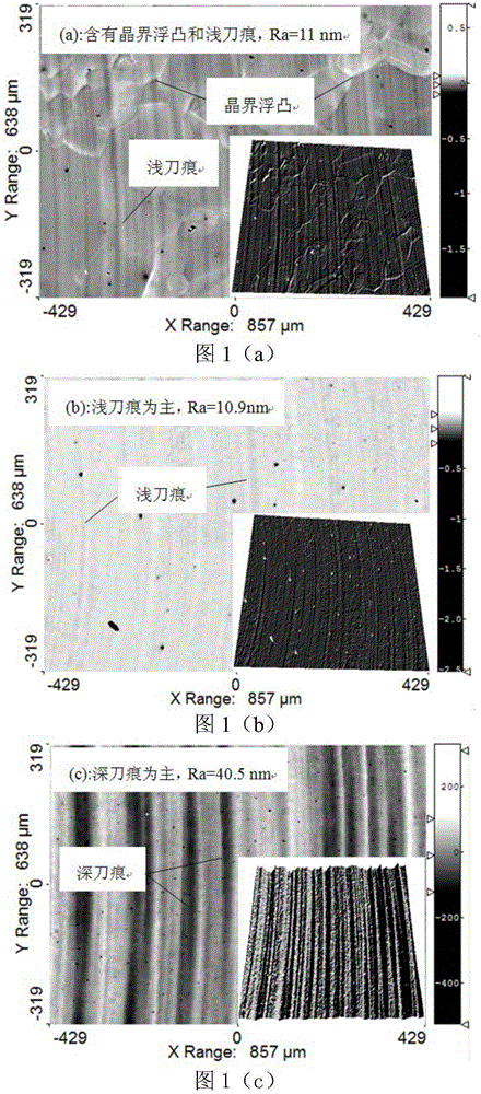
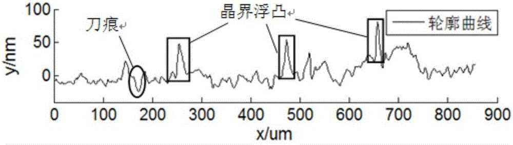
[0032] When cutting oxygen-free copper with single-point diamond, three different surfaces will be obtained according to different cutting parameters, such as figure 1 As shown, the three surfaces are represented as: figure 1 (a) It contains both shallow knife marks and embossed grain boundaries, and its cross-sectional contour line is as follows figure 2 , figure 1 (b) Contains only shallow knife marks, figure 1 (c) Contains only deep tool marks; the cutting parameters that can cause grain boundary embossment are generally: spindle speed 1000-1200r / min, depth of cut 1-5um, feed rate 1-2mm / min; The roughnesses were 11.0 nm, 10.9 nm, and 40.5 nm, respectively. figure 1 (a) with fig...


PUM


Abstract

The invention provides a novel method for effectively representing ultra-precision cutting surface grain-boundary relief. According to the novel method, a band elimination filtering method is coupled with a size method in the fractal dimension concept; by utilization of band elimination filtering, cutter mark signal interference can be effectively reduced and grain-boundary relief information can be highlighted; and meanwhile, the sinuosity of a surface profile can be effectively represented by adopting the size method in the fractal dimension concept. By adoption of the novel method provided by the invention, the problem that when a cutter mark and the grain-boundary relief information exist on an ultra-precision cutting oxygen-free copper surface simultaneously, the difference between the cutter mark and the grain-boundary relief information cannot be distinguished through traditional measuring of the roughness is solved. Therefore, the novel method has the advantages that the characteristics of grain-boundary relief can be effectively recognized, and information about the morphological feature of an ultra-precision machining surface in the micro scale can be quantitatively reflected.

Description

technical field [0001] The invention belongs to the technical field of ultra-precision cutting, and in particular relates to a new method for characterizing grain boundary relief on the surface of ultra-precision cutting. Background technique [0002] Ultra-precision cutting technology usually uses ultra-precision machine tools and single-point diamond tools to process materials. Unlike traditional cutting, in the process of single-point diamond cutting, due to the extremely small cutting depth, it can be regarded as a cutting edge with a certain radius. The cutting process of the blunt round tool, so the surface quality after processing is usually high, the surface roughness can reach tens of nanometers or even several nanometers, and the processed surface is easy to achieve a mirror effect; on the other hand, in the single-point diamond cutting process, the cutting depth is generally microns The cutting process is basically carried out inside the microstructure of the mate...

Claims


Application Information

Patent Timeline
Patent Type & Authority Applications(China)
IPC IPC(8): B23P17/02
CPCB23P17/02
Inventor 帅茂兵杨洋王罡俞建超周婷婷李遥郭亚昆
Owner MATERIAL INST OF CHINA ACADEMY OF ENG PHYSICS
Why Eureka
Try Eureka