Automatic precise clamp and production line for piston machining

A piston, automatic technology, applied in the direction of manufacturing tools, metal processing equipment, metal processing mechanical parts, etc., can solve the problems of high maintenance cost, high use cost, increased maintenance difficulty of structure and system, and achieve simplified structure and control system design. , The mechanical running path is single, and the effect of eliminating the hidden danger of positioning quality

Active Publication Date: 2017-01-11
强哲菲
View PDF6 Cites 2 Cited by
  • Summary
  • Abstract
  • Description
  • Claims
  • Application Information

AI Technical Summary

Problems solved by technology

[0008] First, the piston grasping needs to be completed by an intelligent manipulator. The intelligent manipulator is mainly composed of a hand mechanism, a motion mechanism, a sensing and position measurement system, and a control system. The contact with the processed surface of the piston not only has very high requirements for the design and manufacture of the intelligent manipulator, but the key is that there are defects such as scratches on the piston surface and deformation of the clamping part in the mechanical clamping.
[0009] The second is the mechanical wear of the hand mechanism of the intelligent manipulator, the fluctuation of the working pressure of the hydraulic system of the movement mechanism, the heavy-duty clamping of the manipulator, etc., which affect the stability of the position accuracy of the manipulator, resulting in the reduction of the positioning accuracy during the piston processing and positioning process, which affects the piston processing. Stable quality
[0010] The third is that the structure of the intelligent manipulator is complex and the degree of intelligence is high, but it is expensive, the investment cost is large, and the use cost is high. The complex structure and system increase the difficulty of maintenance, and the later maintenance cost is also high.
[0011] The fourth is pull-type clamping and positioning. The clamping force of the piston's notch is not uniform, which affects the positioning effect and has a certain impact on the machining accuracy of the piston.

Method used


Image

  • Automatic precise clamp and production line for piston machining
  • Automatic precise clamp and production line for piston machining
  • Automatic precise clamp and production line for piston machining

Examples


Embodiment Construction

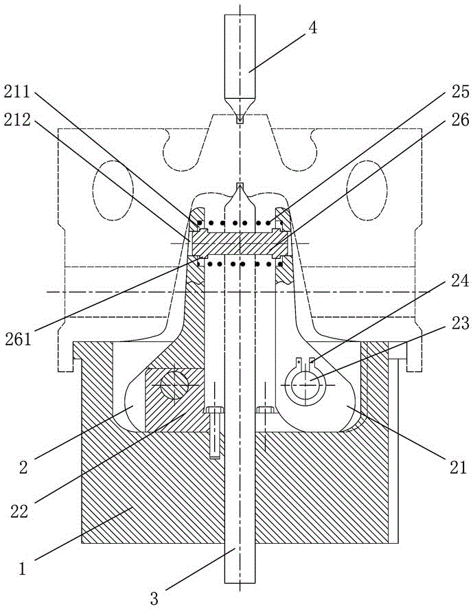
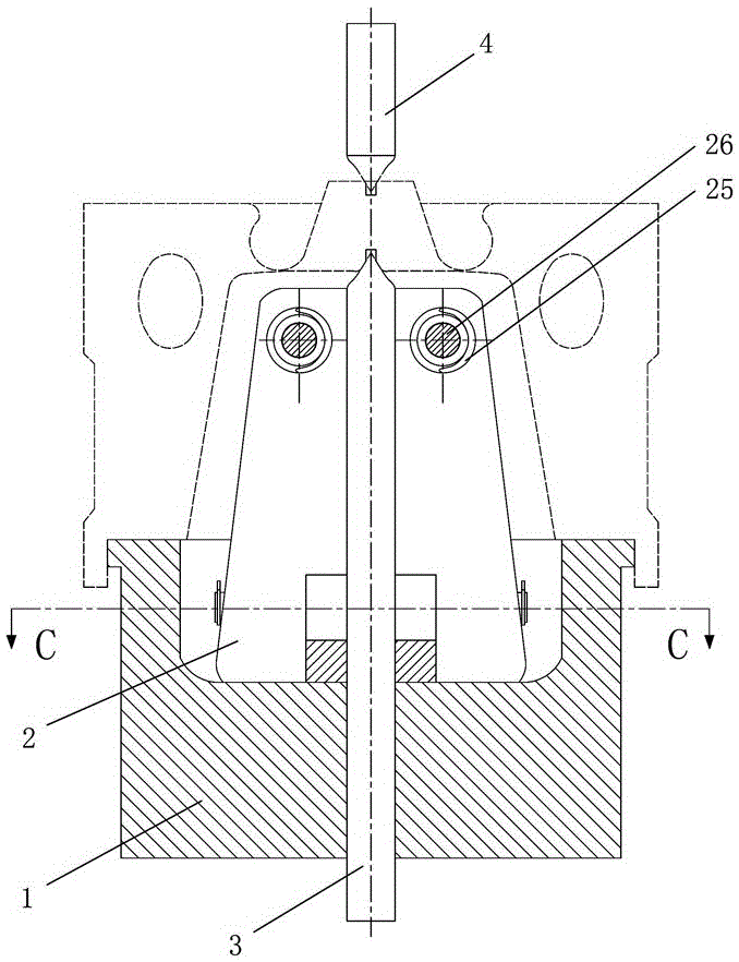
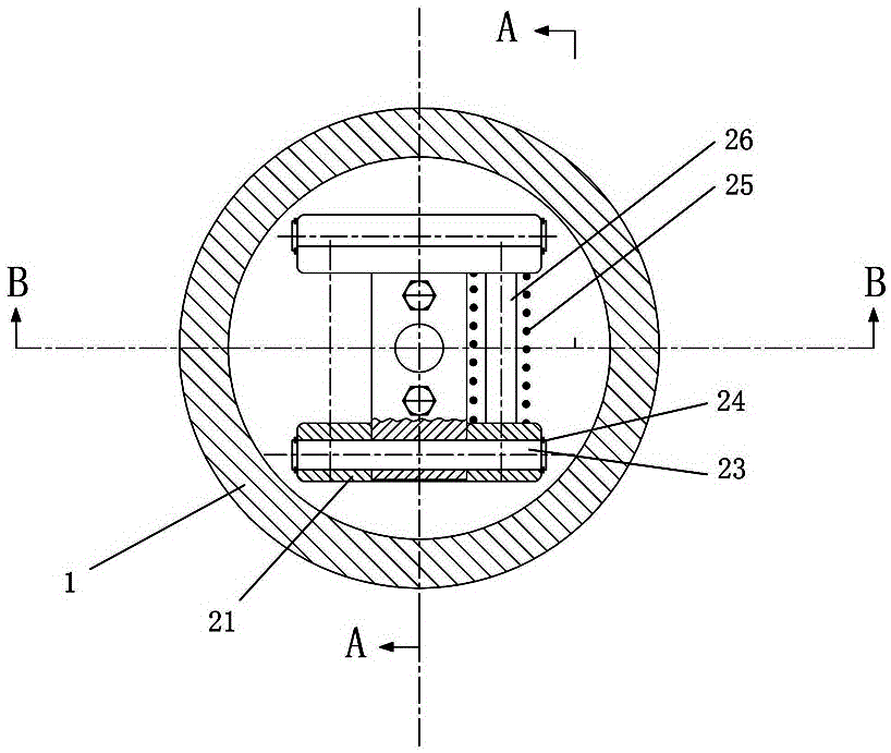
[0037] Figure 1 to Figure 3It shows the embodiment of the first automatic finishing fixture used for piston processing in the present invention. The automatic finishing fixture includes a stop plate 1 and a shift fork assembly 2. The mouth plate 1 is connected, and the fixture also includes a ejector rod 3 and a push rod 4 arranged coaxially with the mouth plate 1. Both the end of the ejector rod 3 and the end of the push rod 4 are provided with a conical top, and the top The material rod 3 is installed in the mouth plate 1 and the shift fork assembly 2, the push rod 4 is arranged above the ejector rod 3, and the conical top of the ejector rod 3 is opposite to the conical top of the push rod 4. The automatic finishing fixture for piston processing of the present invention provides a unique piston clamping method, which ensures that the piston processing surface can be well protected during the positioning and clamping process of the piston, and the main working surface of the...


PUM


Abstract

The invention discloses an automatic precise clamp and production line for piston machining. The clamp comprises a spigot plate and a shifting fork assembly, the upper end of the shifting fork assembly can expand pistons open, and the lower end of the shifting fork assembly is connected with the spigot plate. The clamp further comprises an ejector rod and a push rod, and the ejector rod and the push rod are coaxial with the spigot plate. The end of the ejector rod and the end of the push rod are each provided with a conical centre. The ejector rod is arranged in the spigot plate and the shifting fork assembly in a penetrating mode, the push rod is arranged above the ejector rod, and the conical centre of the push rod is opposite to the conical centre of the push rod. The production line comprises a plurality of machining devices which are connected through a track. A trolley for transporting the piston workpieces is arranged on the track. The machining devices are provided with the automatic precise clamp for piston machining, and the automatic precise clamp is used for loading and unloading the piston workpieces between the trolley and the machining devices. The automatic precise clamp and production line for piston machining have the advantages that the structure is simple, the clamping precision and clamping efficiency are high, the cost input is low, and popularization is facilitated.

Description

technical field [0001] The invention relates to a jig for piston processing, in particular to an automatic finishing jig and a production line for piston processing. Background technique [0002] In order to meet the requirements of diesel engine emission regulations and improve the fuel economy of diesel engines, pistons are the key components of diesel engines. On the one hand, we must continue to carry out basic research on pistons to fully improve their design and processing accuracy and mechanical strength. On the other hand, we must continue to improve production automation. level to reduce manufacturing costs. [0003] The piston automatic machining process route is: rough turning outer circle, flat end face; finishing turning seam, drill head center hole; drilling oil return hole; rough boring pin hole, pin hole chamfering, turning ring groove; pin hole inner Chamfering; Semi-finishing outer circle, Finishing top surface, Finishing second and third ring grooves; Tur...

Claims


Application Information

Patent Timeline
Patent Type & Authority Applications(China)
IPC IPC(8): B23Q3/00
CPCB23Q3/00B23Q2703/10
Inventor 强哲菲
Owner 强哲菲
Why Eureka
Try Eureka