Method for manufacturing abrasive pattern arrangement brazed grinding wheel based on laser pre-fusion covering

A pattern arrangement and abrasive technology, applied in grinding devices, manufacturing tools, grinding/polishing equipment, etc., can solve the problems of difficult coating of binders and abrasives, difficult to achieve complex pattern arrangement, low efficiency, etc. The effect of avoiding high-deficiency defects such as abrasives, improving production efficiency, and improving grinding characteristics

Active Publication Date: 2017-01-11
HUAQIAO UNIVERSITY
View PDF2 Cites 3 Cited by
  • Summary
  • Abstract
  • Description
  • Claims
  • Application Information

AI Technical Summary

Problems solved by technology

However, there are still many problems, which are mainly reflected in: (1) Due to the influence of the production of mesh screens and orifice plates, complex pattern arrangements are difficult to achieve; (2) The method of mesh screens and orifice plates is mainly used in the grinding of flat grinding discs preparation, but obviously helpless for the preparation of grinding wheels with shapes such as arc surfaces; (3) due to the small holes in mesh screens and orifice plates, it is difficult to coat bonding agents and abrasives, so the efficiency of existing methods is very low
Because of this, although the abrasive pattern arrangement has been proposed for many years, it is still unable to see the large-scale impact

Method used


Image

  • Method for manufacturing abrasive pattern arrangement brazed grinding wheel based on laser pre-fusion covering
  • Method for manufacturing abrasive pattern arrangement brazed grinding wheel based on laser pre-fusion covering
  • Method for manufacturing abrasive pattern arrangement brazed grinding wheel based on laser pre-fusion covering

Examples


Embodiment 1

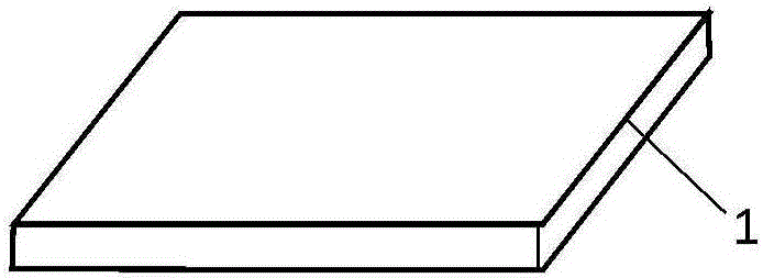
[0029] Step 1, spread the bonding agent 2 evenly on the grinding wheel base 1, such as Figure 1 to Figure 4 , the bonding agent 2 is preferably NiCrBSi powder, and the grinding wheel base 1 is preferably No. 45 steel.

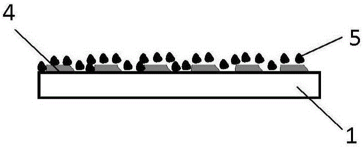
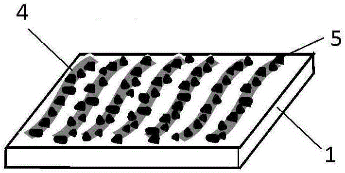
[0030] Step 2, using YAG pulsed laser 3 to perform area scanning cladding heating on the bonding agent 2 according to the designed abrasive arrangement pattern, so that the bonding agent heated by laser scanning is melted and forms a cladding layer 4, such as Figure 5 and Figure 6 As shown, the peak power of the pulsed laser is 200w, the pulse width is 5ms, the pulse frequency is 30Hz, and the scanning speed is 20mm / min.

[0031] Step 3: After the laser scanning is completed, the unscanned heating bond is removed, and the cladding layer 4 is ground to a constant thickness, with a thickness of 50um, so that a cladding layer 4 of equal height is formed on the upper surface of the grinding wheel base, such as Figure 7 and Figure 8 shown.

[0032] Step 4, ...

Embodiment example 2

[0034] Step 1, spread the bonding agent 2 evenly on the grinding wheel base 1, such as Figure 1 to Figure 4 , The bonding agent 2 is preferably NiCrP powder, and the grinding wheel base 1 is preferably 40CrMo steel.

[0035] Step 2, using a continuous laser to scan and clad the bonding agent 2 according to the designed abrasive arrangement pattern, so that the bonding agent heated by laser scanning melts and forms a cladding layer 4; Figure 5 and Figure 6 As shown, the laser power is 120w, the spot diameter is 1.5mm, and the scanning speed is 20mm / min.

[0036] Step 3: After the laser scanning is completed, the unscanned heating bonding agent is removed, and the cladding layer 4 is ground to a fixed thickness, with a thickness of 150um, so that a cladding layer 4 of equal height is formed on the upper surface of the grinding wheel base, such as Figure 7 and Figure 8 shown.

[0037] Step 4, coating a layer of viscose on the upper surface of the grinding wheel base 1, a...

Embodiment example 3

[0039] Step 1, spread the bonding agent 2 evenly on the grinding wheel base 1, such as Figure 1 to Figure 4 , the bonding agent 2 is preferably AgCuTi powder, and the grinding wheel base 1 is preferably No. 45 steel.

[0040] Step 2, using YAG pulsed laser 3 to perform area scanning cladding heating on the bonding agent 2 according to the designed abrasive arrangement pattern, so that the bonding agent heated by laser scanning is melted and forms a cladding layer 4, such as Figure 5 and Figure 6 As shown, the laser peak power is 200w, the pulse width is 5ms, the pulse frequency is 30Hz, and the scanning speed is 20mm / min.

[0041] Step 3: After the laser scanning is completed, the unscanned heating bond is removed, and the cladding layer 4 is ground to a constant thickness, with a thickness of 125um, so that a cladding layer 4 of equal height is formed on the upper surface of the grinding wheel base, such as Figure 7 and Figure 8 shown.

[0042] Step 4, sprinkle cubic...


PUM

PropertyMeasurementUnit
diameteraaaaaaaaaa
diameteraaaaaaaaaa

Abstract

The invention discloses a method for manufacturing an abrasive pattern arrangement based on laser pre-fusion covering. The method includes the steps that firstly, a work face of a grinding wheel base body is coated with binding agents; secondly, a laser focusing spot is driven to conduct scanning and fusion covering heating on the binding agents according to the abrasive arranged patterns, and therefore the binding agents heated by lasers are melted and form a fixedly-connected fusion covering layer with the grinding wheel base body; thirdly, the binding agents not heated through laser fusion covering are removed, the upper surface of the fusion covering layer is cut to be flat, and therefore the thickness of the fusion covering layer is consistent; and fourthly, abrasives are scattered and planted on the work face of the grinding wheel base body, the grinding wheel base body is subjected to heating, heat preservation and cooling in sequence, the abrasives located on the fusion covering layer are bonded to the fusion covering layer, and finally the abrasives not bonded to the fusion covering layer are removed. The advantage that numerical control is used for driving the lasers to conduct local selective fusion covering is sufficiently utilized so that manufacturing of grinding discs with complex abrasive patterns arranged can be achieved; melting and connecting of diamond are achieved through the fixed-thickness binding agent fusion covering layer, and therefore the grinding characteristic of the grinding wheel is effectively improved; and the problem about positioning and the problems of mesh blocking and the like generated during template and screen method implementation are solved, and the manufacturing efficiency is greatly improved.

Description

technical field [0001] The invention relates to a method for making abrasive patterns and arranging brazed grinding wheels based on laser pre-cladding, which belongs to the field of abrasive tool preparation. Background technique [0002] Grinding is the main processing method for precision forming and high-quality surface of mechanical parts, and it is widely used in efficient and precise processing of metals, ceramics, optical crystals and other materials. For grinding processing, the grinding wheel is extremely important to the processing process and the surface quality of the processed workpiece as well as the processing cost, and is the key to efficient and precise grinding technology. Since grinding actually achieves the overall removal of workpiece material through the removal of a small amount of material by many abrasives solidified on the surface of the grinding wheel, the distribution of abrasives on the surface of the grinding wheel has a great impact on the perf...

Claims


Application Information

Patent Timeline
Patent Type & Authority Applications(China)
IPC IPC(8): B24D18/00
CPCB24D18/0072
Inventor 黄国钦郭佳杰王颖达黄辉郭桦徐西鹏
Owner HUAQIAO UNIVERSITY
Why Eureka
Try Eureka