
Automobile spare part cooling device

A technology for auto parts and cooling devices, applied in quenching devices, heat treatment equipment, furnaces, etc., can solve the problems of uncontrollable and inconvenient removal of auto parts into the oil tank or water tank.

Active Publication Date: 2017-01-11
重庆新钰立金属科技有限公司
View PDF7 Cites 5 Cited by
  • Summary
  • Abstract
  • Description
  • Claims
  • Application Information

AI Technical Summary

Problems solved by technology

[0004] In order to solve the problem that the process of auto parts entering the oil tank or water tank cannot be controlled, and it is inconvenient to take out after the oil tank or water tank is cooled, the present invention provides a cooling device for auto parts

Method used


Image

  • Automobile spare part cooling device
  • Automobile spare part cooling device

Examples


Embodiment Construction

[0016] The present invention will be described in further detail below by means of specific embodiments:

[0017] The reference signs in the accompanying drawings of the specification include:

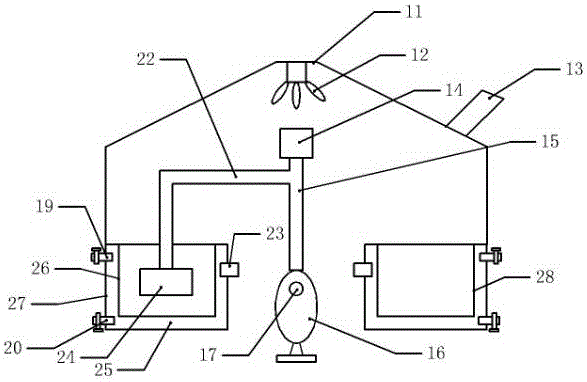
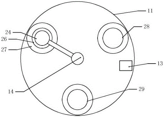
[0018] Smoke hood 11, high-speed fan 12, exhaust port 13, stepper motor 14, stirring shaft 15, cam 16, rotating shaft 17, liquid outlet 19, liquid inlet 20, right-angle connecting rod 22, circulation pump 23, storage tank 24. Circulation pipeline 25, oil tank 26, cooling cabin body 27, acetone tank 28, water tank 29.

[0019] Such as figure 1 Shown auto parts cooling device comprises oil tank 26, water tank 29 and acetone tank 28, oil tank 26 and water tank 29 periphery are provided with cooling cabin body 27, the bottom of cooling cabin body 27 is provided with sound-absorbing sponge, oil tank 26 and water tank 29 and cooling A circulating pipeline 25 is arranged between the cabins 27, a circulating pump 23 is installed on the cooling cabin 27, a liquid inlet 20 and a liquid outlet ...


PUM


Abstract

The invention belongs to the technical field of quenching equipment, and particularly relates to a novel quenching cooling system. The system comprises an oil groove and a water groove, a cooling cabin body is arranged on the outer side of the oil groove and the water groove, a circulating pipeline is arranged between the oil groove and the cooling cabin body, a circulating pipeline is arranged between the water groove and the cooling cabin body, a circulating pump is arranged on the cooling cabin body, a liquid inlet and a liquid outlet are formed in the cooling cabin body, the liquid inlet and the liquid outlet are each provided with a valve, and the device further comprises a storage groove, a right-angle connecting rod, a stirring shaft, a cam and a rotating shaft; a motor is fixedly mounted at the upper end of the stirring shaft, the lower end of the stirring shaft makes contact with the cam, the cam is fixedly connected with the rotating shaft, one end of the right-angle connecting rod is fixed to the stirring shaft, and the other end of the right-angle connecting rod is fixedly provided with a storage groove. The problems that the process that automobile spare parts enter the oil groove or water groove cannot be controlled, and after the oil groove or water groove is cooled, taking is not convenient are solved.

Description

technical field [0001] The invention belongs to the technical field of quenching equipment, in particular to a cooling device for auto parts. Background technique [0002] Quenching is a metal heat treatment process in which the metal workpiece is heated to an appropriate temperature and kept at a constant temperature for a period of time, and then quickly immersed in a cooling medium for rapid cooling. Commonly used quenching media include salt water, water, mineral oil, air, etc. Quenching can improve the hardness and wear resistance of the surface and core of metal workpieces, so it is widely used in the processing of various parts that require surface wear resistance, such as gears, Rolls, carburized parts, etc. Because there are many types of metal workpieces, some workpieces only need one quenching medium to complete their heat treatment process, while some workpieces need two quenching mediums to cool twice to complete the heat treatment process, which can effectivel...

Claims


Application Information

Patent Timeline
Patent Type & Authority Applications(China)
IPC IPC(8): C21D1/64C21D9/00
CPCC21D1/64C21D9/0062
Inventor 陈建国
Owner 重庆新钰立金属科技有限公司
Learn More