Dual-redundancy electric steering engine

An electric steering gear and dual redundancy technology, applied in the direction of electric components, electrical components, electromechanical devices, etc., can solve the problems of unable to use high-power motors, objects controlled by steering gears, and limited multi-level output power, etc. Linear motion performance, improved reliability, compact structure

Active Publication Date: 2017-01-11
NORTHWESTERN POLYTECHNICAL UNIV
View PDF5 Cites 24 Cited by
  • Summary
  • Abstract
  • Description
  • Claims
  • Application Information

AI Technical Summary

Problems solved by technology

Because most of the electric steering gear is in the frequent real-time working state in flight control, especially under the condition of high frequency and high aerodynamic load, it is prone to failure, which will cause the object controlled by the steering gear to lose control, causing serious harm and economic loss
At the same time, due to the limitation of the installation space of the steering gear, the electric steering gear cannot use high-power motors, resulting in limited multi-stage output power
At present, the commonly used electric steering gear systems are mostly double-redundant designs: that is, the double-redundancy design of the drive circuit or the double-redundancy design of the motor windings, but the steering gear is realized by using dual motors plus a planetary differential gear train and a planetary roller screw pair. There are few examples of double-redundancy design; patent CN202364049U discloses "a dual-motor drive device for steering gear", which uses ordinary screw nuts to drive, and the direction of the output shaft is perpendicular to the direction of the motor spindle, the stroke is short, and the load-carrying capacity Limited and not easy to install and maintain

Method used


Image

  • Dual-redundancy electric steering engine
  • Dual-redundancy electric steering engine
  • Dual-redundancy electric steering engine

Examples


Embodiment Construction

[0025] In flight control, the electric steering gear system is mostly in the frequent real-time working state, especially under the condition of high frequency and high aerodynamic load, in order to prevent the motor in the electric steering gear Loss of control threatens the safety of the aircraft and pilots, causing unnecessary losses; at the same time, in order to install electric steering gear with a larger power range in the narrow steering gear installation space of the aircraft, the power range of the flight control system is widened, and the system’s performance is improved. Reliability, this example further elaborates on the dual redundancy electric steering gear.

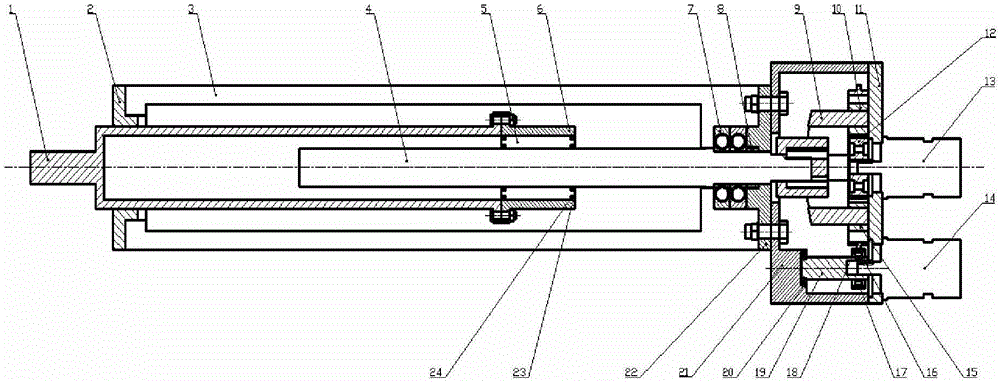
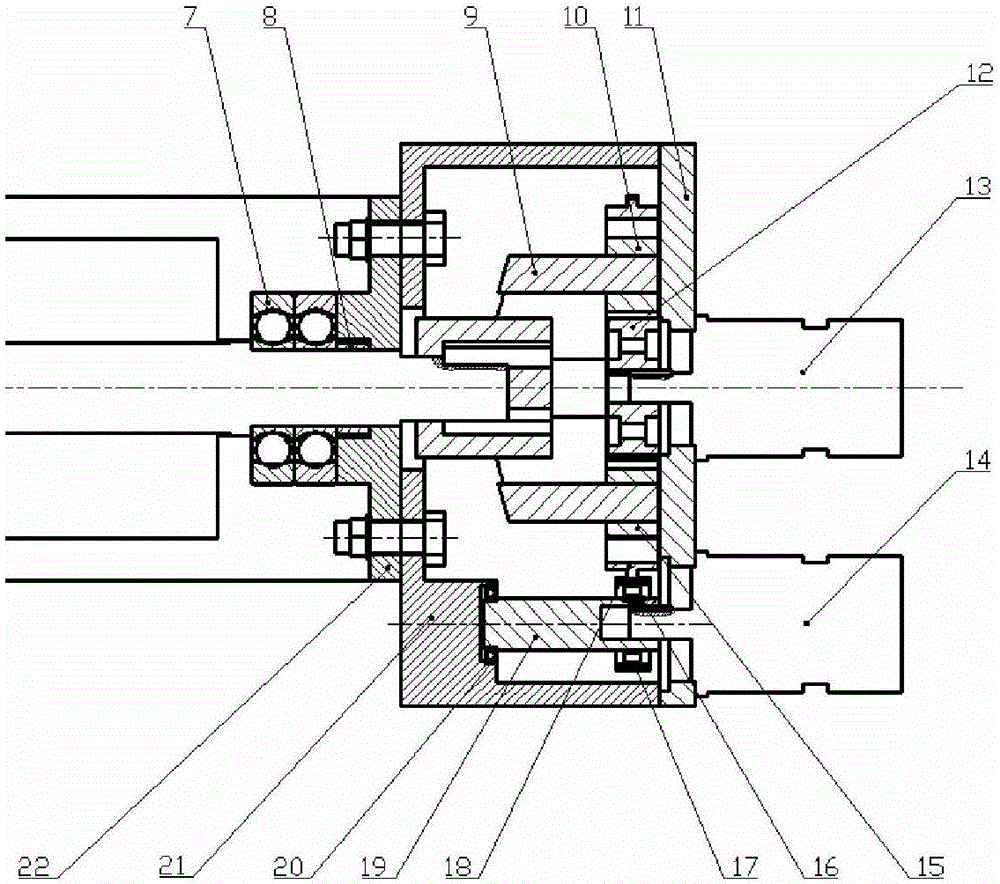
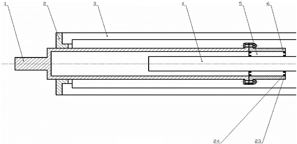
[0026] refer to Figure 1 to Figure 7 In this example, the double-redundancy electric steering gear consists of a planetary gear transmission reduction mechanism, a planetary roller screw pair, a sleeve push rod 1, an actuator end cover 2, a housing 3, a reducer rear cover 11, and a reducer shell body 21,...


PUM


Abstract

The invention discloses a dual-redundancy electric steering engine which is composed of two motors, a planetary gear transmission reducing mechanism, a planetary pin roller lead screw pair and a sleeve push rod; the working principle of a planetary differential gear train is utilized to transmit movement from the two motors to the sleeve push rod through driving the planetary pin roller lead screw pair by the planetary gear transmission reducing mechanism, and rotary movement of a lead screw is converted to straight reciprocating motion of the sleeve push rod through revolution and rotation of a pin roller. The dual-redundancy motors and the planetary pin roller lead screw pair are adopted for driving to realize large stroke and ensure straight line actuation property of an actuator; the planetary pin roller lead screw pair has the characteristics of high carrying capacity and accurate positioning of reciprocating motion; when one motor breaks down, the other motor can still drive a system to act normally so as to improve the reliability of the system; when the two motors work normally, power confluence is realized to provide larger input power for the system; and the dual-redundancy electric steering engine is simple in structure, convenient to maintain and excellent in speed regulation property.

Description

technical field [0001] The invention belongs to the technical field of electric steering gear, and in particular relates to a dual-redundancy electric steering gear driven by a motor. Background technique [0002] Steering gear is actually a position follow-up system. According to different power sources, the widely used steering gear system can be divided into: pneumatic steering gear, hydraulic steering gear and electric steering gear. Compared with pneumatic steering gear and hydraulic steering gear, the electric steering gear system has the characteristics of high reliability, high efficiency, light weight and better maintainability. Therefore, the electric steering gear system will become an important direction for the development of the steering gear system in the future. [0003] The rapid development of UAV requires its control system to have high precision, high sensitivity and high reliability. The steering gear system is an indispensable key component of the fli...

Claims


Application Information

Patent Timeline
Patent Type & Authority Applications(China)
IPC IPC(8): F16H37/12H02K7/116
CPCF16H37/12H02K7/116
Inventor 马尚君李晓风刘更佟瑞庭张鹏涛
Owner NORTHWESTERN POLYTECHNICAL UNIV
Why Eureka
Try Eureka