Two-electrode distributed micro gyroscope with side-discrete adjacent ring and its preparation method
A micro gyroscope and side electrode technology, which is applied to gyroscope/steering sensing equipment, gyro effect for speed measurement, instruments, etc. The effect of reducing parasitic capacitance and improving detection accuracy
- Summary
- Abstract
- Description
- Claims
- Application Information
AI Technical Summary
Problems solved by technology
Method used
Image
Examples
Embodiment 1
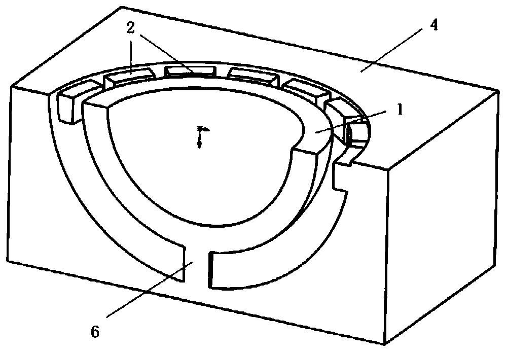
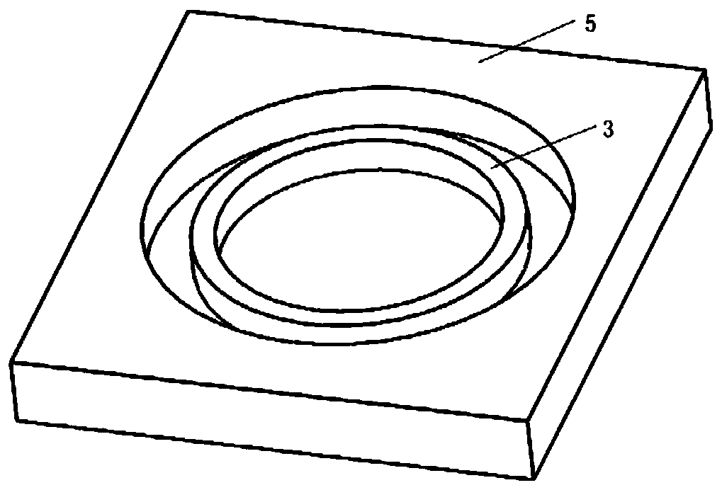
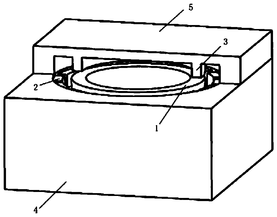
[0057] Such as Figure 1(a)-Figure 1(c) As shown, this embodiment provides a two-electrode distributed micro hemispherical resonator gyroscope with side discrete adjacent surfaces, including: a hemispherical micro resonator 1; sixteen uniformly distributed side electrodes 2; a ring integrated Formula adjacent electrode 3; a single crystal silicon substrate 4; a glass substrate 5; a central fixed support column 6; wherein:
[0058] One end of the central fixed support column 6 is connected to the monocrystalline silicon substrate 4, and the other end of the central fixed support column 6 is connected to the micro-resonator 1 (as shown in Figure 1(a)); 16 The uniformly distributed side electrodes 2 are arranged on the surface of the single crystal silicon substrate 4 (as shown in Figure 1(b)), and are evenly distributed on the upper side of the micro-resonator 1 (as shown in Figure 1(b) c) ); one annular integral adjacent electrode 3 is disposed on the surface of the glass subst...
Embodiment 2
[0070] Such as Figure 2(a)-Figure 2(c) As shown, the present embodiment provides a two-electrode distributed micro-ring resonator gyroscope with side-discrete adjacent surfaces ring, including: a ring-shaped micro-resonator 1; sixteen uniformly distributed side electrodes 2; a ring-shaped integrated Adjacent electrode 3; a single crystal silicon substrate 4; a glass substrate 5; a central fixed support column 6; wherein:
[0071] One end of the central fixed support column 6 is connected to the monocrystalline silicon substrate 4, and the other end of the central fixed support column 6 is connected to the micro-resonator 1 (as shown in Figure 2(a)); 16 One of the uniformly distributed side electrodes 2 is arranged on the surface of the single crystal silicon substrate 4, and is evenly distributed on the outside of the micro-resonator 1 (as shown in FIG. 2(a)); one of the rings is integrated Adjacent electrodes 3 are arranged on the surface of the glass substrate 5 (as shown ...
Embodiment 3
[0079] Such as Figure 3(a)-Figure 3(c) As shown, the present embodiment provides a two-electrode distributed micro-disk resonator gyroscope with side-discrete adjacent surfaces, including: a disc-shaped micro-resonator 1; sixteen uniformly distributed side electrodes 2; An annular one-piece adjacent electrode 3; a single crystal silicon substrate 4; a glass substrate 5; a central fixed support column 6; wherein:
[0080] One end of the central fixed support column 6 is connected to the monocrystalline silicon substrate 4, and the other end of the central fixed support column 6 is connected to the micro-resonator 1 (as shown in Figure 3(a)); 16 One of the uniformly distributed side electrodes 2 is arranged on the surface of the single crystal silicon substrate 4, and is evenly distributed on the outside of the micro-resonator 1 (as shown in FIG. 3(a)); one of the rings is integrated Adjacent electrodes 3 are arranged on the surface of the glass substrate 5 (as shown in Figure...
PUM
| Property | Measurement | Unit |
|---|---|---|
| thickness | aaaaa | aaaaa |
| radius | aaaaa | aaaaa |
| thickness | aaaaa | aaaaa |
Abstract
Description
Claims
Application Information
 - R&D
- Intellectual Property
- Life Sciences
- Materials
- Tech Scout
- Unparalleled Data Quality
- Higher Quality Content
- 60% Fewer Hallucinations
Browse by: Latest US Patents, China's latest patents, Technical Efficacy Thesaurus, Application Domain, Technology Topic, Popular Technical Reports.
© 2025 PatSnap. All rights reserved.Legal|Privacy policy|Modern Slavery Act Transparency Statement|Sitemap|About US| Contact US: help@patsnap.com


