Photo-thermal power generation heat transfer and storage medium leakage detection system and method

A heat storage medium and leakage detection technology, which is applied in the direction of detecting the appearance of fluid at the leakage point, measuring devices, and material analysis through optical means, can solve problems such as leakage at installation points, avoid direct damage, and reduce failures. Links, display results intuitive effect

Inactive Publication Date: 2017-01-11
横河电机(中国)有限公司北京研究开发中心
View PDF0 Cites 4 Cited by
  • Summary
  • Abstract
  • Description
  • Claims
  • Application Information

AI Technical Summary

Problems solved by technology

During the detection process, the metal probe of the detector needs to be directly exposed to the gas medium, so the container containing the gas medium needs to be damaged and then installed. Due to problems such as the aging of the UV emitter, it is necessary to perform regular cal...

Method used


Image

  • Photo-thermal power generation heat transfer and storage medium leakage detection system and method
  • Photo-thermal power generation heat transfer and storage medium leakage detection system and method

Examples


Embodiment 1

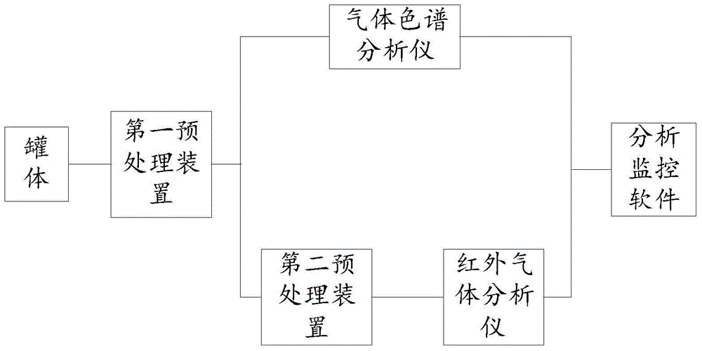
[0037] In order to improve the safety and operability of the leakage detection of the photothermal power generation heat storage heat transfer medium, the present invention proposes a photothermal power generation heat transfer heat storage medium leakage detection system, such as figure 1 As shown, the detection system includes: a tank body, a first preprocessing device, a gas chromatographic analyzer, a second preprocessing device, an infrared gas analyzer, and an analysis and monitoring module.

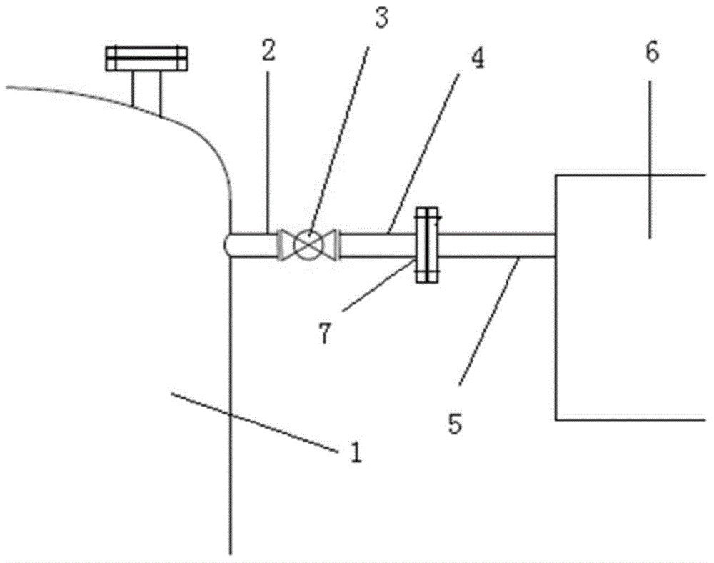
[0038] Such as figure 2 As shown, the tank body 1 is located near the exhaust port of the molten salt tank, so that it is possible to determine whether there is leakage of the heat transfer and heat storage medium by detecting the gas composition in the tank body 1 . At least one tank exhaust pipe 2 is fixed on the tank body 1, the tank exhaust pipe 2 is fixedly connected to one end of the air pressure balance valve 3, and the other end of the air pressure balance valve 3 is fixed...

Embodiment 2

[0054] Correspondingly, the present invention also provides a method for detecting leakage of photothermal power generation heat transfer heat storage medium, the method comprising the following steps:

[0055] The gas medium in the tank is obtained through the air pressure balance valve installed on the tank;

[0056] performing a first pretreatment on the gas medium, the first pretreatment including pressurization and heat preservation pretreatment;

[0057] And the gas medium after processing is divided into two paths and sent to gas chromatograph analyzer and infrared gas analyzer respectively;

[0058] Adopt gas chromatographic analyzer to detect C in the gas medium 12 content;

[0059] Carry out a second pretreatment on the gas medium sent to the infrared gas analyzer, the second pretreatment includes condensing the condensables in the gas medium, and then sending the second pretreated gas medium to the infrared gas Analyzer;

[0060] Use an infrared gas analyzer to ...


PUM


Abstract

A photo-thermal power generation heat transfer and storage medium leakage detection system provided by the present invention comprises a tank body, a first pre-processing device, a gas chromatographic analyzer, a second pre-processing device, an infrared gas analyzer and an analysis monitoring module. The tank body is equipped with at least one air pressure balance valve, the first pre-processing device is used to pre-process a gas medium discharged by the air pressure balance valve and divides the pre-processed gas medium into two to send to the gas chromatographic analyzer and the infrared gas analyzer respectively, and the analysis monitoring module obtains the data detected by the gas chromatographic analyzer and the infrared gas analyzer, and displays, records and analyzes the detection data. According to the present invention, the tank body and a detection device are connected together in a detachable manner, thereby avoiding the direct damage to the tank body, reducing the fault links, and improving the maneuverability of the detection system.

Description

technical field [0001] The invention relates to the technical field of gas leakage detection, in particular to a system and method for detecting leakage of a photothermal power generation heat storage heat transfer medium. Background technique [0002] The solar trough concentrating power plant is composed of three parts: the trough reflector field part, the heat transfer heat storage part and the thermal power plant. The trough mirror field is responsible for tracking the sun and focusing the heat on the heat collecting pipe. The heat on the heat collecting pipe will exchange heat energy to the thermal power plant through the heat transfer part (HTF). If enough heat energy is collected, it will be transferred to the heat storage system. (TES) for storage and backup, and finally reaches the thermal power plant to generate high-temperature and high-pressure steam to drive the steam turbine to generate electricity. [0003] The heat transfer part is a pressure circuit, and it...

Claims


Application Information

Patent Timeline
IPC IPC(8): G01M3/04G01N30/02G01N21/3504
Inventor 李来智郭建新赵磊张翠芳王继富乔靖玉关琪
Owner 横河电机(中国)有限公司北京研究开发中心
Why Eureka
Try Eureka