Suspension imaging optical film

An imaging optics and thin film technology, applied in optics, optical components, instruments, etc., can solve the problems of unrestricted microlens array position coordinate relationship, large overall thickness of imaging film, and difficult cutting of imaging film, etc., to achieve optimal light collection ability, The effect of overcoming the limitations of pattern design and large process tolerance

Active Publication Date: 2017-01-11
SHINE OPTOELECTRONICS KUNSHAN CO LTD
View PDF13 Cites 4 Cited by
  • Summary
  • Abstract
  • Description
  • Claims
  • Application Information

AI Technical Summary

Problems solved by technology

The structure mentioned in the patent has three defects: 1. Since the transmission microlens array is used, the total thickness of the micro-focusing unit layer, the transparent spacer layer and the graphic structure layer will be greater than the aperture of the micro-focusing element; 2. There is no limit The positional coordinate relationship between the microlens array and the microtext array located on the first surface of the substrate. From a scientific point of view, in many cases, this structur

Method used


Image

  • Suspension imaging optical film
  • Suspension imaging optical film
  • Suspension imaging optical film

Examples


Embodiment Construction

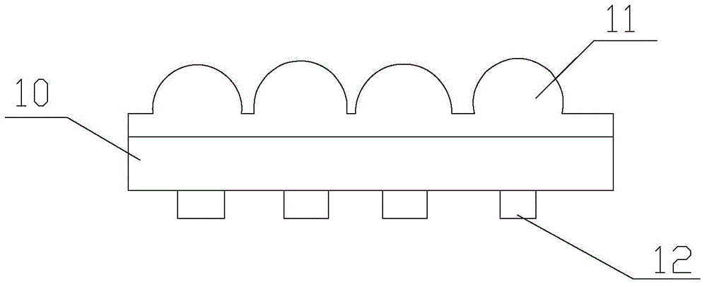
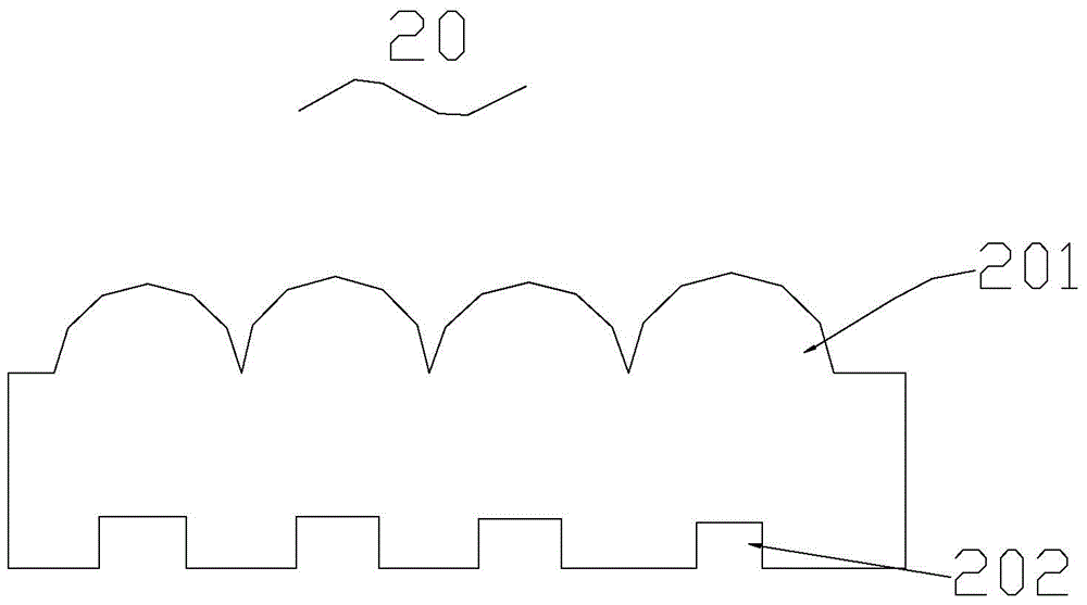
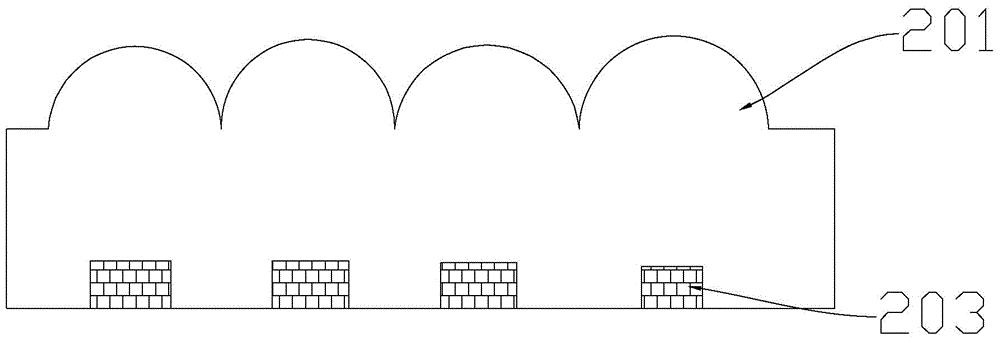
[0074] In order to facilitate the understanding of the present invention, the present invention will be described more fully below with reference to the associated drawings. Preferred embodiments of the invention are shown in the accompanying drawings. However, the present invention can be implemented in many different forms and is not limited to the embodiments described below. On the contrary, the purpose of providing these embodiments is to make the disclosure of the present invention more thorough and comprehensive.

[0075] It should be noted that when an element is referred to as being “disposed on” another element, it may be directly on the other element or there may also be an intervening element. When an element is referred to as being "connected to" another element, it can be directly connected to the other element or intervening elements may also be present. The terms "vertical," "horizontal," "left," "right," and similar expressions are used herein for purposes o...


PUM

PropertyMeasurementUnit
Thicknessaaaaaaaaaa
Diameteraaaaaaaaaa
Focal lengthaaaaaaaaaa

Abstract

Disclosed is a suspension imaging optical film. The film comprises a first polymer having a first surface and a second polymer having a second surface, wherein the first surface is opposite to the second surface. A microlens structure is formed on the first surface and comprises a plurality of microfocusing units. A cavity structure is formed on the second surface, and several image-text structures imaged by the microlens structure are stored in the cavity structure. A fusion part is formed at the adjacent parts of the first polymer and the second polymer, in order to allow the microlens structure to be integral with the cavity structure. The microfocusing units fit the image-text structures, so that when the suspension imaging optical film is observed from the side of the image-text structure or the microfocusing unit, a suspension image that is suspended on the suspension imaging optical film is formed. The suspension image suspended on the suspension imaging optical film is a single channel pattern or a multi-channel pattern. The purpose of reducing the thickness of the suspension imaging optical film is achieved.

Description

technical field [0001] The invention relates to the technical field of suspended imaging optical films, in particular to a suspended imaging optical film. Background technique [0002] Various 3D imaging technologies are attracting more and more attention in the fields of information, display, medical treatment, and military affairs. The use of microlens technology to achieve three-dimensional imaging has great potential and prospects. It is developed from the integrated photography proposed by G. Lippman in 1908. A group of two-dimensional unit images with different perspective relations of the three-dimensional scene are recorded by a lens array and image acquisition, without special observation glasses and lighting, the three-dimensional image of the original scene can be directly observed in front of the display microlens array. With the development of microlens array manufacturing process and the popularization of high-resolution printing and image sensors, integrated...

Claims


Application Information

Patent Timeline
IPC IPC(8): G02B27/22G02B1/10
CPCG02B1/10G02B30/27
Inventor 张健
Owner SHINE OPTOELECTRONICS KUNSHAN CO LTD
Why Eureka
Try Eureka